Return to Section TOC
Return to Section TOC
Return to Master TOC
Return to Master TOC
TROUBLESHOOTING AND REPAIR | ||
|
| |
|
|
|
DRIVE MOTOR TEST (continued)
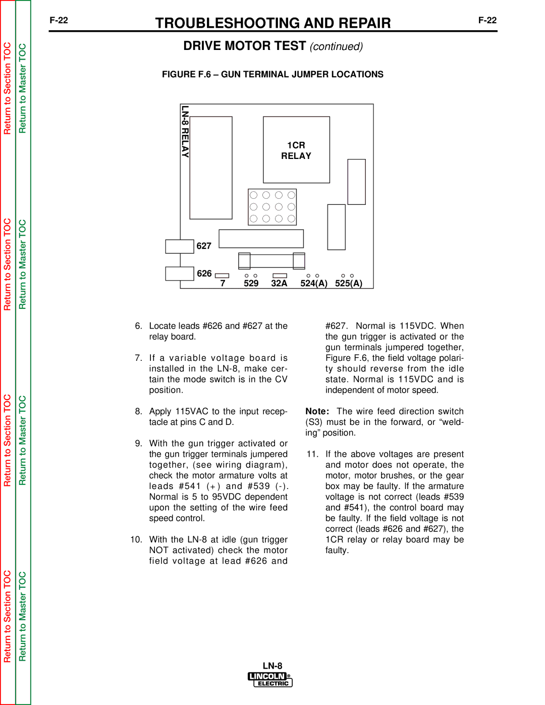
FIGURE F.6 – GUN TERMINAL JUMPER LOCATIONS
|
|
|
|
| |
|
|
| |||
RELAY |
|
|
| 1CR | |
|
|
|
| ||
|
|
|
| RELAY | |
|
|
|
|
|
|
|
|
|
|
|
|
|
|
|
|
|
|
|
|
|
|
|
|

 627
627
626 |
|
|
|
|
7 | 529 | 32A | 524(A) | 525(A) |
Return to Section TOC
Return to Master TOC
6.Locate leads #626 and #627 at the relay board.
7.If a variable voltage board is installed in the
8.Apply 115VAC to the input recep- tacle at pins C and D.
9.With the gun trigger activated or the gun trigger terminals jumpered together, (see wiring diagram), check the motor armature volts at leads #541 (+) and #539
10.With the
#627. Normal is 115VDC. When the gun trigger is activated or the gun terminals jumpered together, Figure F.6, the field voltage polari- ty should reverse from the idle state. Normal is 115VDC and is independent of motor speed.
Note: The wire feed direction switch (S3) must be in the forward, or “weld- ing” position.
11.If the above voltages are present and motor does not operate, the motor, motor brushes, or the gear box may be faulty. If the armature voltage is not correct (leads #539 and #541), the control board may be faulty. If the field voltage is not correct (leads #626 and #627), the 1CR relay or relay board may be faulty.
Return to Section TOC
Return to Master TOC