MDrive17Plus MICROSTEPPING
STANDARD SPECIFICATIONS
INPUT VOLTAGE (+V) | Range | +12 to +48 VDC |
| |
Power supply current requirements = 2A (maximum) per MDrive17Plus. | ||||
|
| Actual power supply current will depend on voltage and load. | ||
| Universal | Voltage Range: +5 to +24 VDC Sourcing or Sinking | ||
| Step Clock, Direction and Enable |
| ||
ISOLATED INPUT |
|
| ||
| Voltage Range: +5 VDC |
| ||
| Differential |
| ||
| Clockwise and Counterclockwise |
| ||
|
|
| ||
| Digital Filter Range | 50 nS to 12.9 µS (10 MHz to 38.8 kHz) | ||
| Clock Types | Step/Direction, Quadrature, Step Up/Step Down, Clockwise/Counterclockwise | ||
| Step Frequency | 2 MHz Default / 5 MHz Max |
| |
MOTION |
| Number of Settings | 20 | |
| Resolution |
| 200, 400, 800, 1000, 1600, 2000, 3200, 5000, | |
| Steps Per Revolution | 6400, 10000, 12800, 20000, 25000, 25600, | ||
|
| 40000, 50000, 51200, 36000 (0.01 deg/µstep), | ||
|
|
| ||
|
|
| 21600 (1 arc minute/µstep), 25400 (0.001mm/µstep) | |
THERMAL | Operating Temperature | Heat Sink | ||
Motor | ||||
|
| |||
SETUP PARAMETERS
| Function | Range | Units | Default | |
MHC | Motor Hold Current | 0 to 100 | percent | 5 | |
MRC | Motor Run Current | 1 to 100 | percent | 25 | |
MSEL | Microstep Resolution | 1, 2, 4, 5, 8, 10, 16, 25, 32, 50, 64, 100, | µsteps per full step | 256 | |
108, 125, 127, 128, 180, 200, 250, 256 | |||||
|
|
|
| ||
DIR | Motor Direction Override | 0/1 | — | CW | |
HCDT | Hold Current Delay Time | 0 or | mSec | 500 | |
CLK TYPE | Clock Type | Step/Dir, Quadrature, Up/Down, CW/CCW | — | Step/Dir | |
CLK IOF | Clock and Direction Filter | 50 nS to 12.9 µS | nS ( MHz) | 200 nS (2.5 MHz) | |
(10 MHz to 38.8 kHz) | |||||
|
|
|
| ||
USER ID | User ID | Customizable | IMS | ||
EN ACT | Enable Active | High/Low | — | High |
All parameters are set using the supplied IMS SPI Motor Interface GUI and may be changed
An optional Communication Converter is recommended with first orders.
MOTOR SPECIFICATIONS
| Holding Torque | Detent Torque | Rotor Inertia | Weight (Motor+Driver) | |
SINGLE LENGTH | 32 | 1.66 | 0.00053 | / 0.038 | 10.4 oz / 294.8 g |
DOUBLE LENGTH | 60 | 2.08 | 0.00080 | / 0.057 | 12.0 oz / 340.2 g |
TRIPLE LENGTH | 74.9 | 3.47 | 0.00116 | / 0.082 | 15.2 oz / 430.9 g |
ENCODER PIN ASSIGNMENTS
External Encoder
| DIFFERENTIAL ENCODER |
|
| with locking connector feature |
|
Pluggable Interface | Function | Function |
Pin 1 | No Connect | Ground |
Pin 2 | +5 VDC Input | Index |
Pin 3 | Ground | Channel A |
Pin 4 | No Connect | +5 VDC Input |
Pin 5 | Channel A – | Channel B |
Pin 6 | Channel A + |
|
Pin 7 | Channel B – |
|
Pin 8 | Channel B + |
|
Pin 9 | Index – |
|
Pin 10 | Index + |
|
Optional encoder cables are available.
Internal Encoder
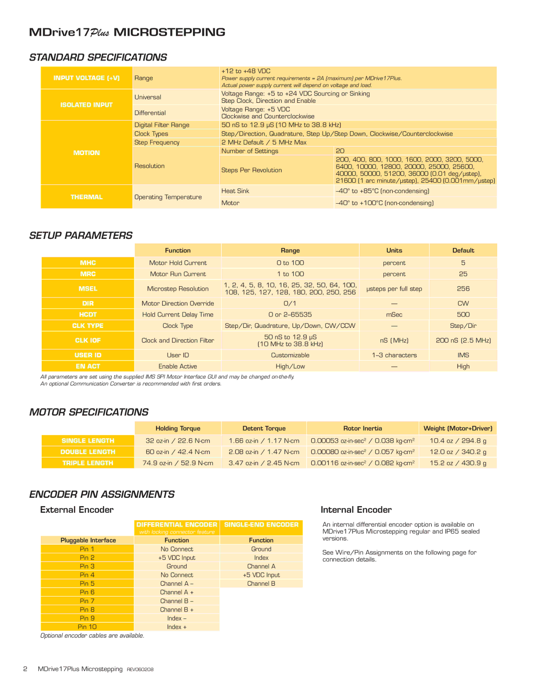
An internal differential encoder option is available on MDrive17Plus Microstepping regular and IP65 sealed versions.
See Wire/Pin Assignments on the following page for connection details.
2 MDrive17Plus Microstepping REV060208
