8 en Install the BasesF220 Series Detectors with
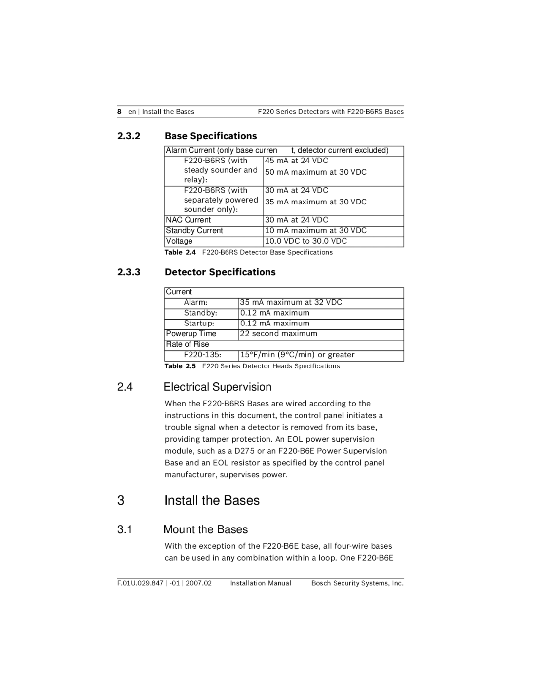
2.3.2 | Base Specifications |
|
|
|
|
| Alarm Current (only base current, detector current excluded) | |
|
|
|
| 45 mA at 24 VDC | |
| steady sounder and | 50 mA maximum at 30 VDC |
| relay): |
|
|
|
|
| 30 mA at 24 VDC | |
| separately powered | 35 mA maximum at 30 VDC |
| sounder only): |
|
|
|
|
| NAC Current | 30 mA at 24 VDC |
|
|
|
| Standby Current | 10 mA maximum at 30 VDC |
|
|
|
| Voltage | 10.0 VDC to 30.0 VDC |
|
|
|
Table 2.4
2.3.3Detector Specifications
Current
Alarm: | 35 mA maximum at 32 VDC |
|
|
Standby: | 0.12 mA maximum |
|
|
Startup: | 0.12 mA maximum |
|
|
Powerup Time | 22 second maximum |
|
|
Rate of Rise |
|
|
|
15°F/min (9°C/min) or greater | |
|
|
Table 2.5 F220 Series Detector Heads Specifications
2.4Electrical Supervision
When the
3 Install the Bases
3.1Mount the Bases
With the exception of the
F.01U.029.847 | Installation Manual | Bosch Security Systems, Inc. |