F220 Series Detectors with
1. Positive (+) and negative |
| Supervision Base or a |
| D275 Power Supervision | |
power either in parallel |
| Module. |
originating from the same | 4. | When connecting a D275, |
power supply or run from |
| connect the positive (+) |
separate power supplies. |
| wire to the yellow input |
2. Positive (+) and negative |
| (24 VDC) and the negative |
| ||
(IDC) from the control |
| (black). The red wire is |
panel or an existing |
| not used. |
circuit. | 5. | The blue wires from the |
3. Interconnection circuit |
| D275 Power Supervision |
(connects Terminal 3 from |
| Module provide power |
base to base) for up to five |
| supervision. |
bases on a common power | 6. | An EOL resistor as |
supply circuit. Each power |
| specified in the control |
circuit must be terminated |
| panel’s installation |
with an |
| instructions. |
|
|
|
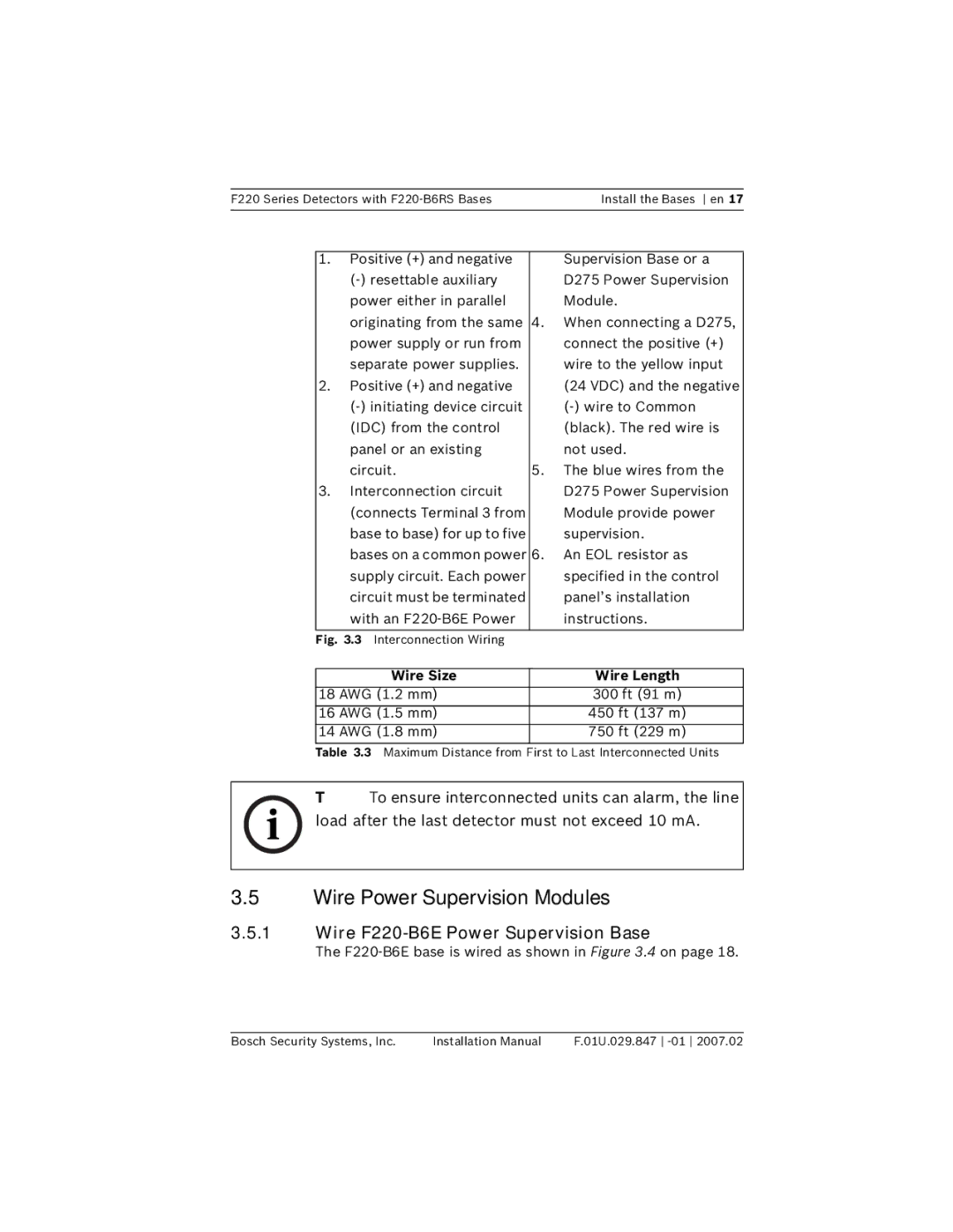
Fig. 3.3 Interconnection Wiring |
|
|
|
|
|
Wire Size |
| Wire Length |
|
|
|
18 AWG (1.2 mm) |
| 300 ft (91 m) |
|
|
|
16 AWG (1.5 mm) |
| 450 ft (137 m) |
|
|
|
14 AWG (1.8 mm) |
| 750 ft (229 m) |
|
|
|
| Table 3.3 Maximum Distance from First to Last Interconnected Units | |
i | NOTE! To ensure interconnected units can alarm, the line | |
load after the last detector must not exceed 10 mA. | ||
|
3.5Wire Power Supervision Modules
3.5.1Wire F220-B6E Power Supervision Base
The F220-B6E base is wired as shown in Figure 3.4 on page 18.
Bosch Security Systems, Inc. | Installation Manual | F.01U.029.847 |
