14 en Install the BasesF220 Series Detectors with
| _ |
|
|
| _ |
1 + |
|
|
| + 1 | |
|
|
|
|
| |
4 | b2 b1 |
|
| 4 | a1/a2 c |
|
|
| |||
| 4 |
|
| C | 5 |
| 5 | 3 |
| NO | |
|
|
|
|
| |
| + |
| 2 | + |
|
3 |
| 1 | 3 | ||
_ |
|
| _ | ||
2 | _+ |
|
| +_ | 2 |
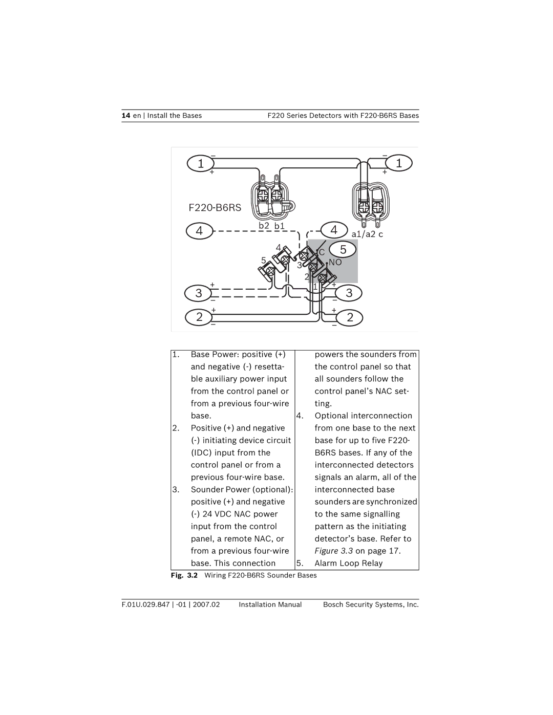
1. Base Power: positive (+) |
| powers the sounders from | |||
and negative |
| the control panel so that | |||
ble auxiliary power input |
| all sounders follow the | |||
from the control panel or |
| control panel’s NAC set- | |||
from a previous |
| ting. |
| ||
base. | 4. | Optional interconnection | |||
2. Positive (+) and negative |
| from one base to the next | |||
| base for up to five F220- | ||||
(IDC) input from the |
| B6RS bases. If any of the | |||
control panel or from a |
| interconnected detectors | |||
previous |
| signals an alarm, all of the | |||
3. Sounder Power (optional): |
| interconnected base | |||
positive (+) and negative |
| sounders are synchronized | |||
| to the same signalling | ||||
input from the control |
| pattern as the initiating | |||
panel, a remote NAC, or |
| detector’s base. Refer to | |||
from a previous |
| Figure 3.3 on page 17. | |||
base. This connection | 5. | Alarm Loop Relay | |||
Fig. 3.2 Wiring F220-B6RS Sounder Bases
F.01U.029.847 | Installation Manual | Bosch Security Systems, Inc. |
