F220 Series Detectors with | Install the Detector Heads en 21 |
|
|
CAUTION! When using the locking bar, before installing
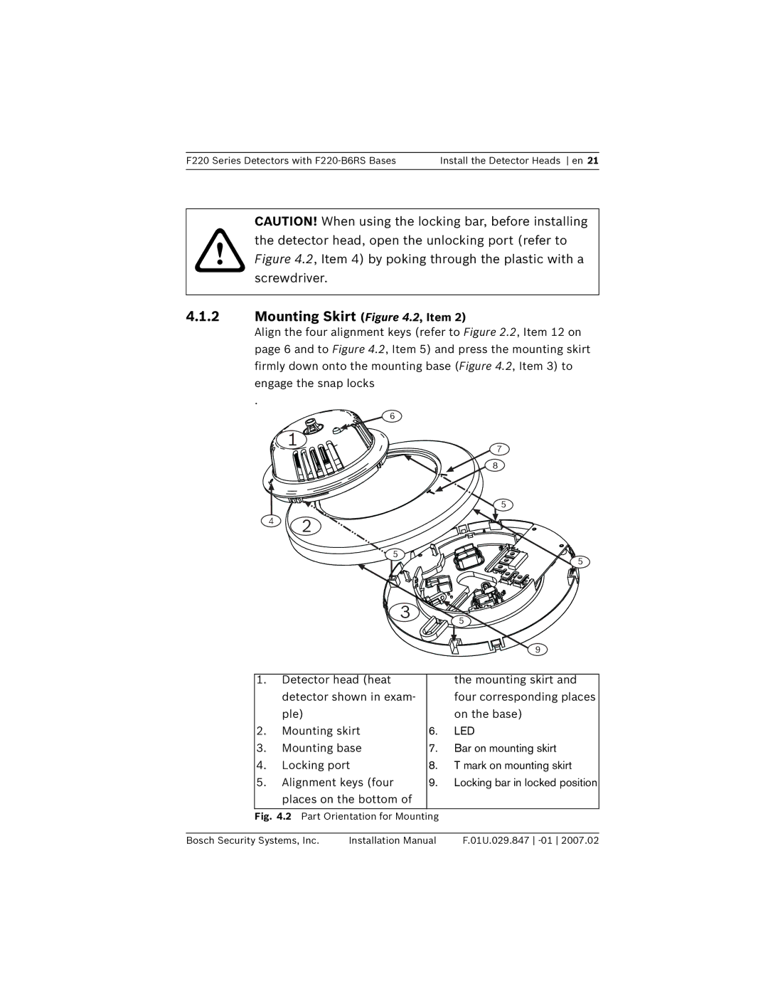
!the detector head, open the unlocking port (refer to Figure 4.2, Item 4) by poking through the plastic with a
screwdriver.
4.1.2Mounting Skirt (Figure 4.2, Item 2)
Align the four alignment keys (refer to Figure 2.2, Item 12 on page 6 and to Figure 4.2, Item 5) and press the mounting skirt firmly down onto the mounting base (Figure 4.2, Item 3) to engage the snap locks
.
6
|
| 1 |
|
| 7 |
|
|
|
|
| |
|
|
|
|
| 8 |
|
| 2 |
|
| 5 |
| 4 |
|
|
| |
|
|
|
|
| |
|
|
| 5 |
| 5 |
|
|
|
|
| |
|
|
| 3 |
| 5 |
|
|
|
|
| |
|
|
|
|
| 9 |
1. |
| Detector head (heat |
| the mounting skirt and | |
|
| detector shown in exam- |
| four corresponding places | |
|
| ple) |
|
| on the base) |
2. |
| Mounting skirt | 6. | LED | |
3. |
| Mounting base | 7. | Bar on mounting skirt | |
4. |
| Locking port | 8. | T mark on mounting skirt | |
5. |
| Alignment keys (four | 9. | Locking bar in locked position | |
|
| places on the bottom of |
|
| |
Fig. 4.2 Part Orientation for Mounting |
| ||||
Bosch Security Systems, Inc. | Installation Manual | F.01U.029.847 | |||
