4 en General Information | F220 Series Detectors with |
|
|
manufacturer’s installation instructions for proper
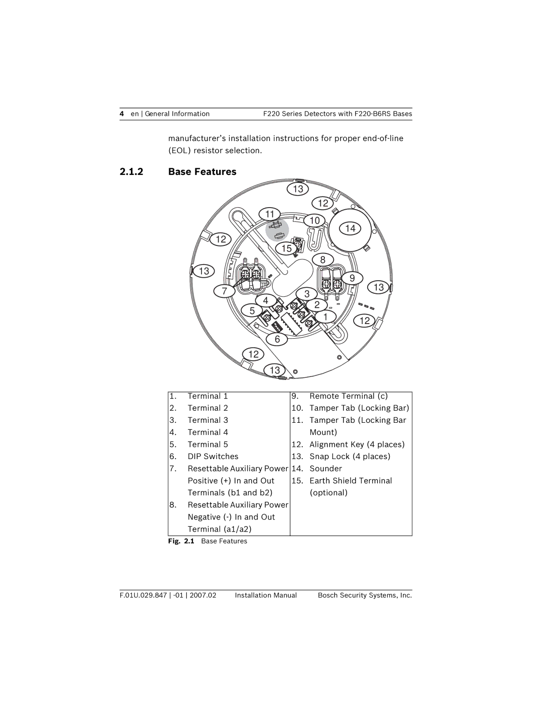
2.1.2Base Features
| 13 | |
11 | 12 | |
10 | ||
| ||
12 | 15 | |
| ||
13 | 8 | |
| ||
7 | 3 | |
4 | 2 | |
5 | ||
1 | ||
4 | ||
3 |
| |
P |
| |
ID | 2 | |
| 1 | |
N |
| |
O |
|
6
12
13
14
9
13
12
1. | Terminal 1 | 9. | Remote Terminal (c) |
2. | Terminal 2 | 10. | Tamper Tab (Locking Bar) |
3. | Terminal 3 | 11. | Tamper Tab (Locking Bar |
4. | Terminal 4 |
| Mount) |
5. | Terminal 5 | 12. | Alignment Key (4 places) |
6. | DIP Switches | 13. | Snap Lock (4 places) |
7. | Resettable Auxiliary Power | 14. | Sounder |
| Positive (+) In and Out | 15. | Earth Shield Terminal |
| Terminals (b1 and b2) |
| (optional) |
8. | Resettable Auxiliary Power |
|
|
| Negative |
|
|
| Terminal (a1/a2) |
|
|
Fig. 2.1 Base Features
F.01U.029.847 | Installation Manual | Bosch Security Systems, Inc. |
