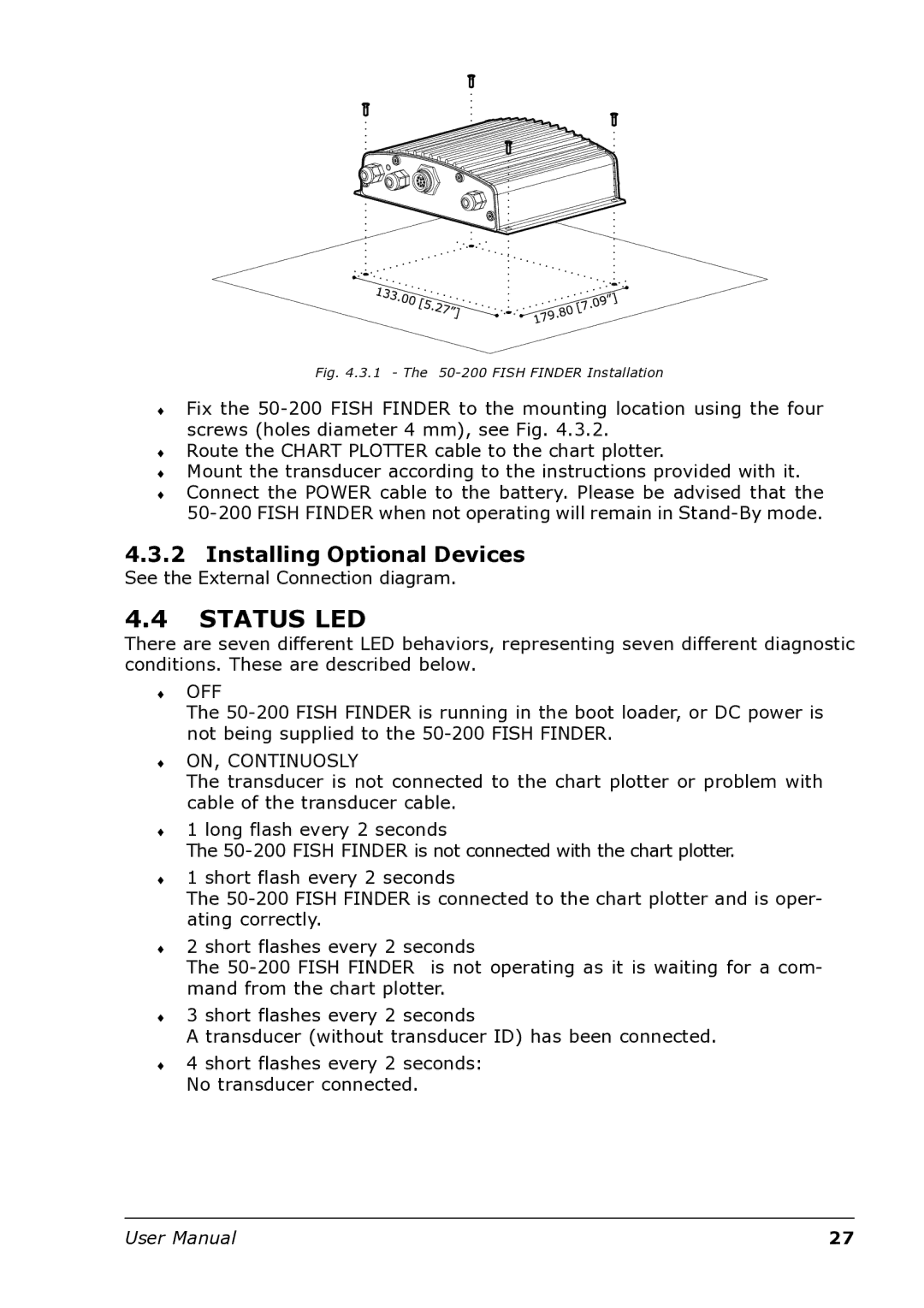
Fig. 4.3.1 - The 50-200 FISH FINDER Installation
♦Fix the
♦Route the CHART PLOTTER cable to the chart plotter.
♦Mount the transducer according to the instructions provided with it.
♦Connect the POWER cable to the battery. Please be advised that the
4.3.2Installing Optional Devices
See the External Connection diagram.
4.4STATUS LED
There are seven different LED behaviors, representing seven different diagnostic conditions. These are described below.
♦OFF
The
♦ON, CONTINUOSLY
The transducer is not connected to the chart plotter or problem with cable of the transducer cable.
♦1 long flash every 2 seconds
The
♦1 short flash every 2 seconds
The
♦2 short flashes every 2 seconds
The
♦3 short flashes every 2 seconds
A transducer (without transducer ID) has been connected.
♦4 short flashes every 2 seconds: No transducer connected.
User Manual | 27 |