ADJUSTING THE NECK SUPPORT
Curved Back and Ulti-Mate Air Back
1.Height Adjustment - Loosen the thumbscrew knob or adjustment lever on the neck support bracket. Loosen the height adjustment stop setscrew. Adjust the neck support to the desired height and retighten the thumbscrew knob or adjustment lever. Slide height adjustment stop to the top of the support bracket and retighten setscrew.
Insert detent pin into through both walls of ver- tical post (Transport Ready Option [TRRO]).
NOTE: The height adjustment stop allows the neck sup- port to be removed for transfers, then reinstalled back to the exact height set by the location of the height adjust- ment stop.
2.Depth Adjustment - Loosen the thumbscrew knob on the horizontal post, adjust the neck support to the desired depth and retighten the thumbscrew knob.
NOTE: On the
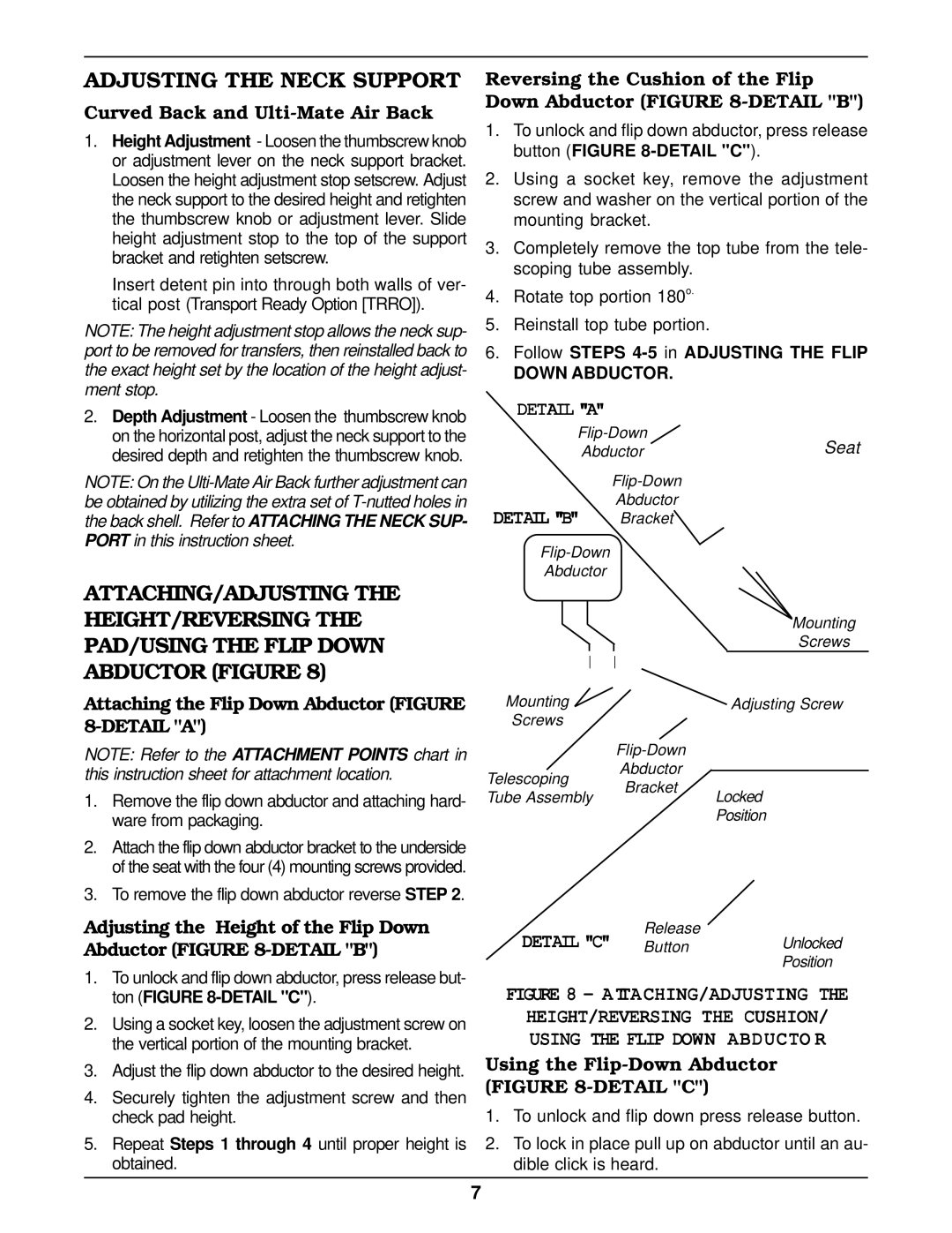
ATTACHING/ADJUSTING THE HEIGHT/REVERSING THE PAD/USING THE FLIP DOWN ABDUCTOR (FIGURE 8)
Attaching the Flip Down Abductor (FIGURE 8-DETAIL "A")
NOTE: Refer to the ATTACHMENT POINTS chart in this instruction sheet for attachment location.
1.Remove the flip down abductor and attaching hard- ware from packaging.
2.Attach the flip down abductor bracket to the underside of the seat with the four (4) mounting screws provided.
3.To remove the flip down abductor reverse STEP 2.
Adjusting the Height of the Flip Down Abductor (FIGURE 8-DETAIL "B")
1.To unlock and flip down abductor, press release but- ton (FIGURE
2.Using a socket key, loosen the adjustment screw on the vertical portion of the mounting bracket.
3.Adjust the flip down abductor to the desired height.
4.Securely tighten the adjustment screw and then check pad height.
5.Repeat Steps 1 through 4 until proper height is obtained.
Reversing the Cushion of the Flip Down Abductor (FIGURE 8-DETAIL "B")
1.To unlock and flip down abductor, press release button (FIGURE
2.Using a socket key, remove the adjustment screw and washer on the vertical portion of the mounting bracket.
3.Completely remove the top tube from the tele- scoping tube assembly.
4.Rotate top portion 180o.
5.Reinstall top tube portion.
6.Follow STEPS
DOWN ABDUCTOR.
DETAIL "A"
Seat | ||
Abductor | ||
|
| |
DETAIL "B" | Abductor |
|
Bracket |
| |
|
| |
Abductor |
|
|
|
| Mounting |
|
| Screws |
Mounting |
| Adjusting Screw |
Screws |
|
|
Abductor
Telescoping Bracket
Tube AssemblyLocked
Position
Release
DETAIL "C" ButtonUnlocked
Position
FIGURE 8 - ATTACHING/ADJUSTING THE
HEIGHT/REVERSING THE CUSHION/ USING THE FLIP DOWN ABDUCTO R
Using the Flip-Down Abductor (FIGURE 8-DETAIL "C")
1.To unlock and flip down press release button.
2.To lock in place pull up on abductor until an au- dible click is heard.
7
