Appendix C – Specification
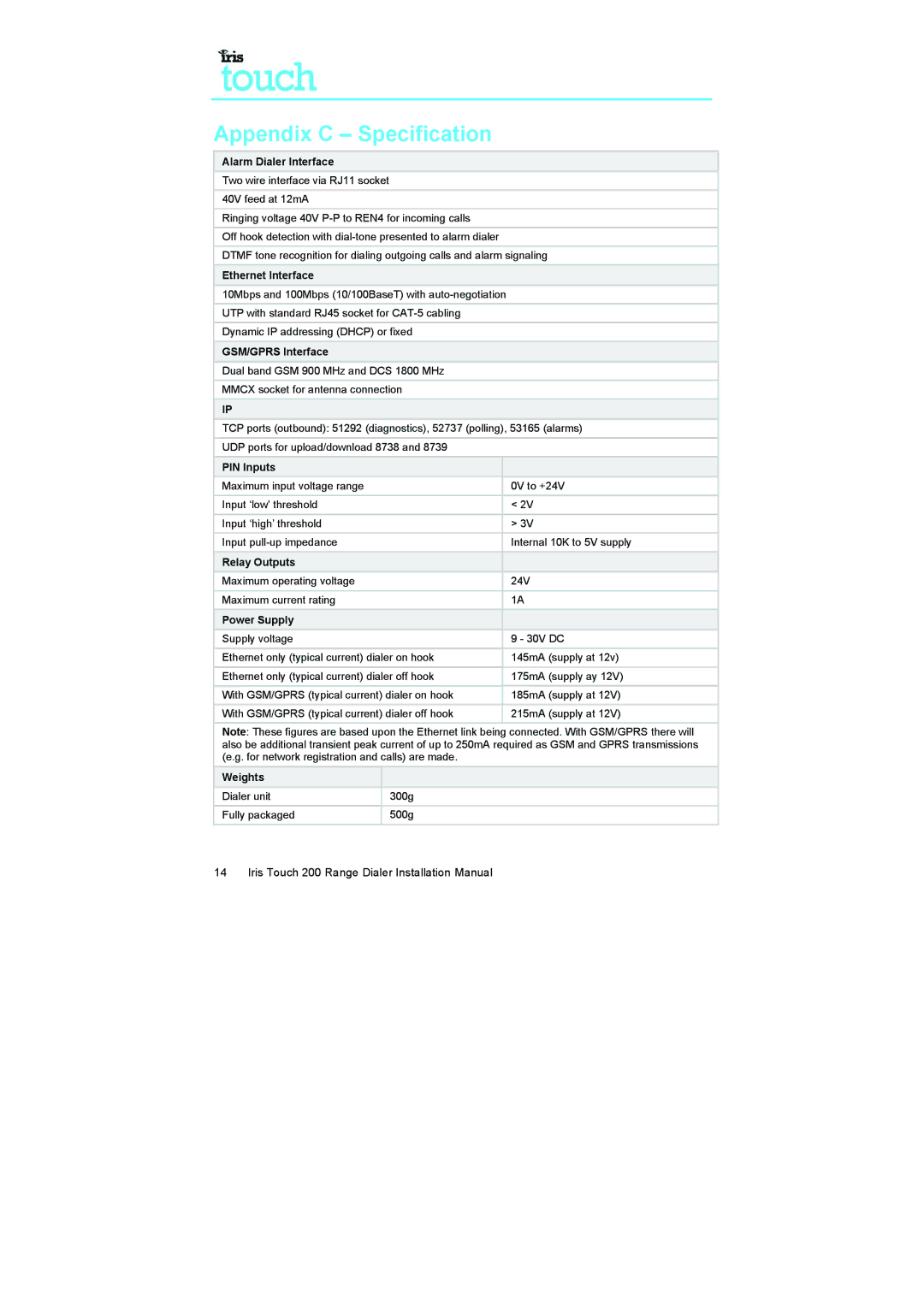
Alarm Dialer Interface
Two wire interface via RJ11 socket
40V feed at 12mA
Ringing voltage 40V
Off hook detection with
DTMF tone recognition for dialing outgoing calls and alarm signaling
Ethernet Interface
10Mbps and 100Mbps (10/100BaseT) with
UTP with standard RJ45 socket for
Dynamic IP addressing (DHCP) or fixed
GSM/GPRS Interface
Dual band GSM 900 MHz and DCS 1800 MHz
MMCX socket for antenna connection
IP
TCP ports (outbound): 51292 (diagnostics), 52737 (polling), 53165 (alarms)
UDP ports for upload/download 8738 and 8739
PIN Inputs |
|
Maximum input voltage range | 0V to +24V |
|
|
Input ‘low’ threshold | < 2V |
|
|
Input ‘high’ threshold | > 3V |
|
|
Input | Internal 10K to 5V supply |
|
|
Relay Outputs |
|
Maximum operating voltage | 24V |
|
|
Maximum current rating | 1A |
|
|
Power Supply |
|
Supply voltage | 9 - 30V DC |
|
|
Ethernet only (typical current) dialer on hook | 145mA (supply at 12v) |
|
|
Ethernet only (typical current) dialer off hook | 175mA (supply ay 12V) |
|
|
With GSM/GPRS (typical current) dialer on hook | 185mA (supply at 12V) |
|
|
With GSM/GPRS (typical current) dialer off hook | 215mA (supply at 12V) |
|
|
Note: These figures are based upon the Ethernet link being connected. With GSM/GPRS there will also be additional transient peak current of up to 250mA required as GSM and GPRS transmissions (e.g. for network registration and calls) are made.
Weights |
|
Dialer unit | 300g |
|
|
Fully packaged | 500g |
|
|