DESCARGA

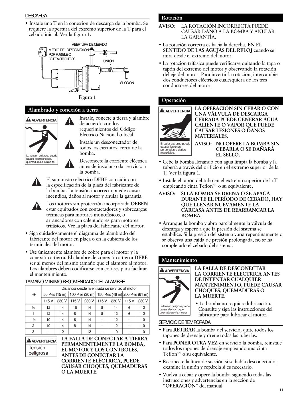
Instale una T en la conexión de descarga de la bomba. Se requiere la apertura del extremo superior de la T para el cebado inicial. Ver la figura 1.

ABERTURA DE CEBADO

MEDIO DE DESCONEXIÓN

POR FUSIBLE O

CORTACIRCUITOSUNIÓN

SUCCIÓN

Figura 1

Rotación

AVISO: LA ROTACIÓN INCORRECTA PUEDE CAUSAR DAÑO A LA BOMBA Y ANULAR LA GARANTÍA.

La rotación correcta es hacia la derecha, EN EL SENTIDO DE LAS AGUJAS DEL RELOJ cuando se mira desde el extremo del motor.

La rotación trifásica puede verificarse quitando la tapa o tapón del extremo del motor y observando la rotación del eje del motor. Para invertir la rotación, intercambie dos conductores eléctricos cualesquiera de los tres conductores del motor.

Operación

Alambrado y conexión a tierra

ADVERTENCIA

LA OPERACIÓN SIN CEBAR O CON UNA VÁLVULA DE DESCARGA

ADVERTENCIA

La tensión peligrosa puede

Instale, conecte a tierra y alambre de acuerdo con los requerimientos del Código Eléctrico Nacional o local.

Instale un desconectador de todos los circuitos, cerca de la bomba.

El calor extremo puede causar lesiones personales o daños materiales.

CERRADA PUEDE GENERAR AGUA CALIENTE O VAPOR QUE PUEDE CAUSAR LESIONES O DAÑOS MATERIALES.

AVISO: NO OPERE LA BOMBA SIN CEBARLA O SE DAÑARÁ EL SELLO.

causar electrochoque, quemaduras o la muerte.

Desconecte la corriente eléctrica antes de instalar o dar servicio a la bomba.

• Cebe la bomba llenando con agua limpia la bomba y la

tubería a través del orificio en el extremo superior de la

T. Ver la figura 1.

El suministro eléctrico DEBE coincidir con la especificación de la placa del fabricante de la bomba. La tensión incorrecta puede causar incendios, daños al motor y anular la garantía.

Los motores sin protección incorporada DEBEN estar equipados con contactadores y sobrecargas térmicas para motores monofásicos, o arrancadores con calentadores para motores trifásicos. Ver la placa del fabricante del motor.

• Siga cuidadosamente el diagrama de alambrado del

fabricante del motor en placa o en la cubierta de los

terminales del motor.

• Use únicamente alambre de cobre para el motor y la

conexión a tierra. El alambre de conexión a tierra DEBE

ser al menos del mismo tamaño que el alambre al motor.

• Instale el tapón del tubo en el extremo superior de la T

empleando cinta Teflon™ o su equivalente.

AVISO: SI LA BOMBA SE DRENA O SE APAGA DURANTE EL PERÍODO DE CEBADO, HAY QUE LLENAR NUEVAMENTE LA CARCASA ANTES DE REARRANCAR LA BOMBA.

Arranque la bomba y abra parcialmente la válvula de descarga y espere a que la presión del sistema se estabilice. Si la presión del sistema varía repentinamente o se observa una caída de presión prolongada, no se ha completado el cebado del sistema.

Mantenimiento

Los alambres deben codificarse con colores para facilitar

el mantenimiento.

TAMAÑO MÍNIMO RECOMENDADO DEL ALAMBRE


Distancia desde la entrada de servicio al motor


HP

50 Pies (15 m)

100 Pies (30 m)

150 Pies (46 m) 200 Pies (61 m)


115 V

230 V

115 V

230 V

115 V

230 V

115 V

230 V


34

12

14

10

14

8

14

6

12

1

12

14

8

14

8

12

6

12

112

10

14

8

14

12

10

ADVERTENCIA

La tensión peligrosa puede causar electrochoque, quemaduras o la muerte.

LA FALLA DE DESCONECTAR

LA CORRIENTE ELÉCTRICA ANTES DE INTENTAR CUALQUIER MANTENIMIENTO, PUEDE CAUSAR CHOQUES, QUEMADURAS O

LA MUERTE.

La bomba no requiere lubricación. Consulte y siga las instrucciones del fabricante para lubricar el motor.

2

10

14

8

14

12

10

3

12

12

10

10


LA FALLA DE CONECTAR A TIERRA

ADVERTENCIA


PERMANENTEMENTE LA BOMBA,

Tensión


EL MOTOR Y LOS CONTROLES,


peligrosa


ANTES DE CONECTAR LA


CORRIENTE ELÉCTRICA, PUEDE


CAUSAR CHOQUES, QUEMADURAS


O LA MUERTE.


SERVICIO DE TEMPORADA

Para RETIRAR la bomba del servicio, quite todos los tapones de drenaje y drene todas las tuberías.

Para PONER OTRA VEZ en servicio la bomba, reinstale todos los tapones de drenaje empleando una cinta Teflon™ o su equivalente.

Reconecte la línea de succión si se había desconectado, examine la unión y repárela si es necesario.

Vuelva a cebar y opere la bomba siguiendo todas las instrucciones y advertencias en la sección de “OPERACIÓN” del manual.

11

Page 11
Image 11
ITT GT30, GT10, GT15, GT20, GT07 specifications Rotación, Operación Alambrado y conexión a tierra, Mantenimiento

GT07, GT15, GT10, GT20, GT30 specifications

The ITT GT series, comprising models GT30, GT20, GT10, GT15, and GT07, is renowned for its advanced engineering and superior performance in the realm of industrial and commercial applications. Each model in the GT series represents a unique blend of technology and design aimed at meeting diverse operational requirements.

The ITT GT30 is one of the flagship models of the series, recognized for its robust performance and reliability. It features a high-capacity design, capable of delivering significant power while maintaining energy efficiency. Key technologies integrated into the GT30 include advanced cooling systems and precision engineering of components, which help minimize wear and tear, thus extending the lifespan of the unit.

The GT20 model stands as a versatile option, striking a balance between power and compact design. With its flexible configuration and modular design, the GT20 can adapt to various settings, making it ideal for applications where space is a constraint. The inclusion of smart technology allows for real-time monitoring, ensuring optimal performance and minimal downtime.

The GT10 model is tailored for those who prioritize efficiency without compromising on output. This model emphasizes energy-saving features, thus making it an excellent choice for eco-conscious businesses. The GT10 is equipped with state-of-the-art power management systems that optimize energy use while delivering consistent performance across multiple applications.

The GT15 combines the strengths of both the GT20 and GT10, offering a balanced solution for mid-range applications. Its design focuses on ease of installation and maintenance, which operators will find advantageous as it reduces operational disruptions. The GT15 also supports advanced connectivity options, providing users with greater control and oversight.

Lastly, the GT07 serves as the entry-level model in the ITT GT series. Despite its smaller size, the GT07 does not compromise on performance. It is engineered for user-friendly operation and reliability, making it suitable for smaller operations or as a supplemental unit in larger systems. The advancements in digital technology embedded within the GT07 ensure that it meets modern standards for performance and safety.

Overall, the ITT GT series epitomizes innovation and quality, with each model designed to cater to specific needs in an ever-evolving industrial landscape. Whether it’s for heavy-duty applications or more compact needs, the GT series delivers an impressive array of features and specifications that underline ITT's commitment to excellence in engineering.