CV-M91
6.2.5. Long time integration
The exposure time is the interval between 2 ext. VD pulses sent to the VD input. (Pin No. 7 of the
Refer to “7. Configuring the Camera.”
To use this mode: |
|
Set function: | Trigger mode to “Long Time integrationl”. SW |
| On PK8407: JP301 open, JP302 short, JP311 short. |
| Accumulation to “Field” or “Frame”. SW |
| Scanning to |
| Shutter Speed to “OFF ”. SW |
| Other functions |
Input: | Ext. VD to pin 7 on |
| (Ext. HD to pin 7 on |
Important notes on using this mode.
•The exposure range is from 1 field to ∞. However it is recommended not to use exposure over 2 seconds due visible dark current signals.
•The ext. VD signal should follow the camera sync system and interlace setting.
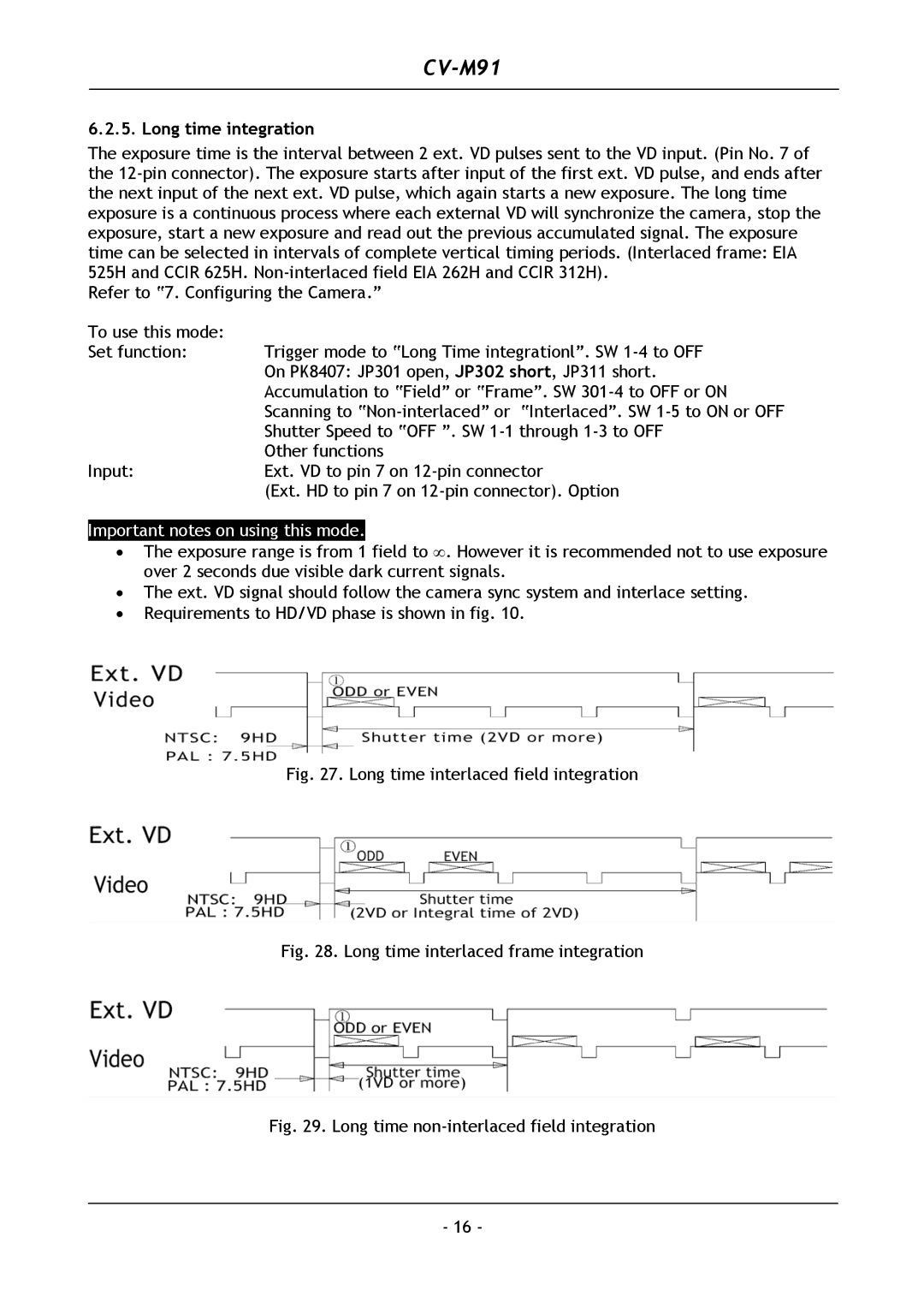
•Requirements to HD/VD phase is shown in fig. 10.
Fig. 27. Long time interlaced field integration
Fig. 28. Long time interlaced frame integration
Fig. 29. Long time non-interlaced field integration
- 16 -