CV-M91
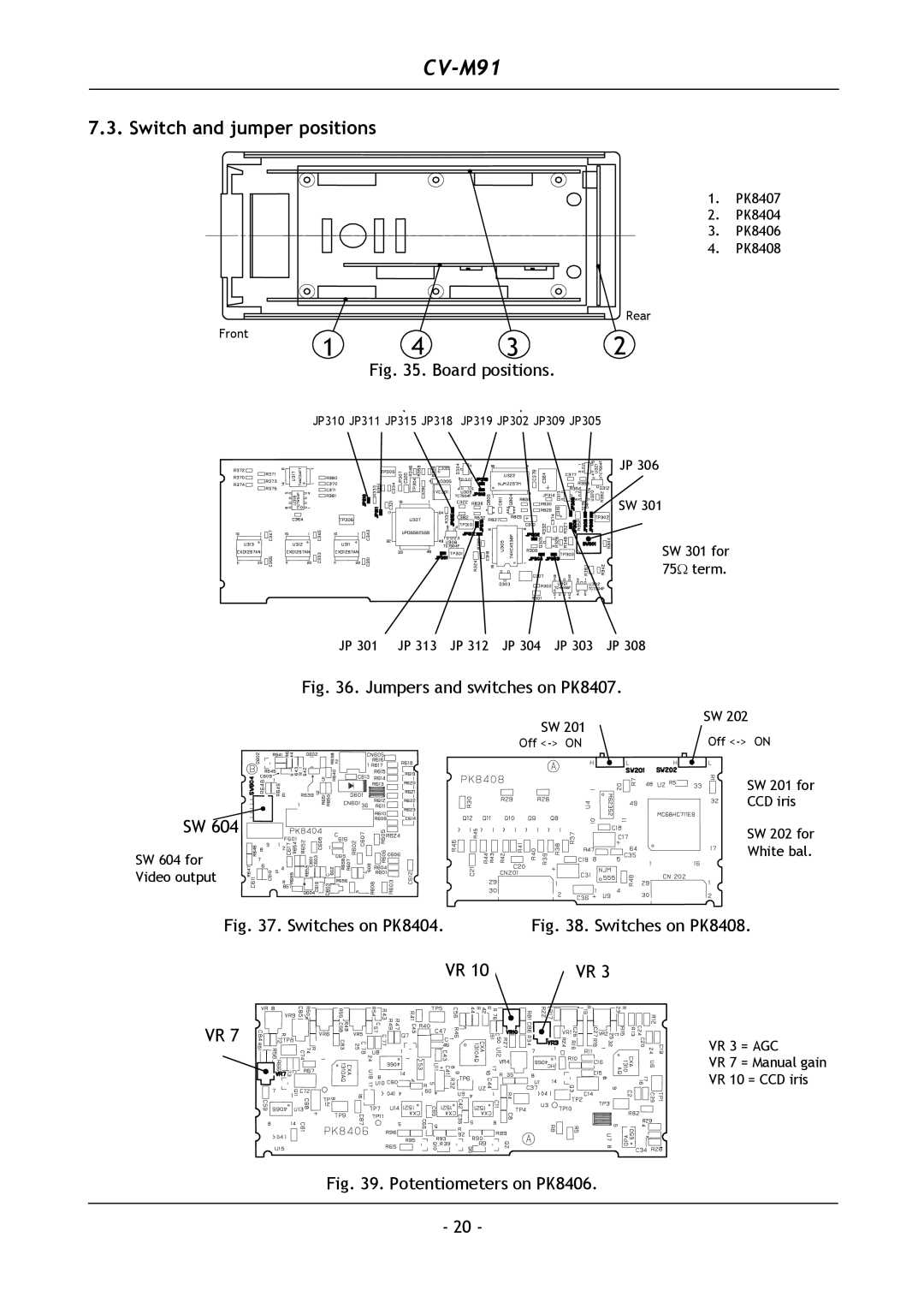
7.3. Switch and jumper positions
1. PK8407
2. PK8404
3. PK8406
4. PK8408
Rear
Front | 1 | 4 | 3 | 2 |
|
Fig. 35. Board positions.
JP310 JP311 JP315 JP318 JP319 JP302 JP309 JP305
JP 306
SW 301
SW 301 for 75Ω term.
JP 301 JP 313 JP 312 JP 304 JP 303 JP 308
Fig. 36. Jumpers and switches on PK8407.
| SW 201 | SW 202 |
| Off | |
| Off | |
|
| SW 201 for |
|
| CCD iris |
SW 604 |
| SW 202 for |
|
| |
SW 604 for |
| White bal. |
|
| |
Video output |
|
|
Fig. 37. Switches on PK8404. | Fig. 38. Switches on PK8408. | |
VR 10 | VR 3 |
|
VR 7 |
| VR 3 = AGC |
|
| |
VR 7 = Manual gain
VR 10 = CCD iris
Fig. 39. Potentiometers on PK8406.
- 20 -