CV-M91
6.2.4. Start Stop Mode
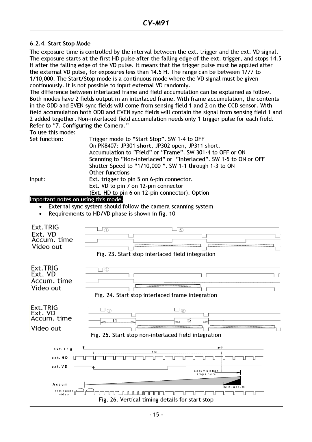
The exposure time is controlled by the interval between the ext. trigger and the ext. VD signal. The exposure starts at the first HD pulse after the falling edge of the ext. trigger, and stops 14.5 H after the falling edge of the VD pulse. It means that the trigger pulse must be applied after the external VD pulse, for exposures less than 14.5 H. The range can be between 1/77 to 1/10,000. The Start/Stop mode is a continuous mode where the VD signal must be given continuously. It is not possible to input external VD randomly.
The difference between interlaced frame and field accumulation can be explained as follow. Both modes have 2 fields output in an interlaced frame. With frame accumulation, the contents in the ODD and EVEN sync fields will come from sensing field 1 and 2 on the CCD sensor. With field accumulation both ODD and EVEN sync fields will contain the signal from sensing field 1 and 2 added together.
To use this mode: |
|
Set function: | Trigger mode to “Start Stop”. SW |
| On PK8407: JP301 short, JP302 open, JP311 short. |
| Accumulation to “Field” or “Frame”. SW |
| Scanning to |
| Shutter Speed to “1/10,000 ”. SW |
| Other functions |
Input: | Ext. trigger to pin 5 on |
| Ext. VD to pin 7 on |
| (Ext. HD to pin 6 on |
Important notes on using this mode.
•External sync system should follow the camera scanning system
•Requirements to HD/VD phase is shown in fig. 10
Fig. 23. Start stop interlaced field integration
Fig. 24. Start stop interlaced frame integration
Fig. 25. Start stop non-interlaced field integration
e x t . T r i g |
1 3 H |
e x t . H D
e x t . V D
A c c u m
c o m p o s it e
v id e o
a c c u m u la t io n
s t o p s h e r e
M in . a c c u m .
Fig. 26. Vertical timing details for start stop
- 15 -