2.2Power Connector
The power and ancillary connections are made via a 9 way D male connector. The power supply input is fully isolated from the chassis of the module.
Note: The power supply cannot be used as an RS232 input line.
|
|
|
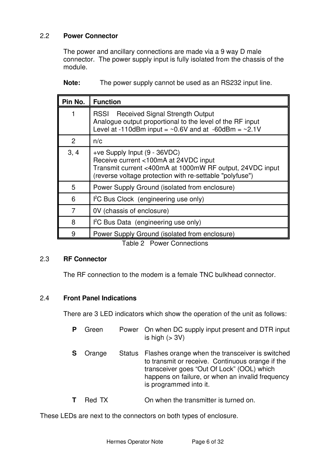
Pin No. | Function |
|
1 | RSSI Received Signal Strength Output |
|
| Analogue output proportional to the level of the RF input |
|
| Level at |
|
|
|
|
2 | n/c |
|
|
|
|
3, 4 | +ve Supply Input (9 - 36VDC) |
|
| Receive current <100mA at 24VDC input |
|
| Transmit current <400mA at 1000mW RF output, 24VDC input |
|
| (reverse voltage protection with |
|
|
|
|
5 | Power Supply Ground (isolated from enclosure) |
|
|
|
|
6 | I2C Bus Clock (engineering use only) |
|
7 | 0V (chassis of enclosure) |
|
|
|
|
8 | I2C Bus Data (engineering use only) |
|
9 | Power Supply Ground (isolated from enclosure) |
|
| Table 2 Power Connections | |
2.3RF Connector
The RF connection to the modem is a female TNC bulkhead connector.
2.4Front Panel Indications
There are 3 LED indicators which show the operation of the unit as follows:
P | Green | Power | On when DC supply input present and DTR input |
|
|
| is high (> 3V) |
S | Orange | Status | Flashes orange when the transceiver is switched |
|
|
| to transmit or receive. Continuous orange if the |
|
|
| transceiver goes “Out Of Lock” (OOL) which |
|
|
| happens on failure, or when an invalid frequency |
|
|
| is programmed into it. |
T | Red TX |
| On when the transmitter is turned on. |
These LEDs are next to the connectors on both types of enclosure.
Hermes Operator Note | Page 6 of 32 |