Series Routers Installation and User Guide
FCC Requirements For Consumer Products
Federal Communications Commission FCC Statement
C. Explanatory Notes Equipment Attachment Limitations
Industry Canada Notice CS-03
Avis CS-03 d’Industrie Canada
EC Declaration of Conformity
Software License AGREEMENTa
Page
Page
Page
Contents
Unpacking and Inspecting E-Series Routers
Cabling E-Series Routers
Xii
Powering Up E-Series Routers
Xiii
Part 2. System and Module Specifications
Xiv
Appendix B Installing JUNOSe Software
Series Routers
About This Guide
Conventions
Audience
Xvi
Icon Meaning Description
Xvii
Documentation
Xviii
Xix
Comments About the Documentation
Contacting Customer Support
Part
Installing and Using E-Series Routers
Page
Overview
Series Overview
1E-series router communicating over T1/T3 lines
Where E-Series Routers Fit
CPE
ERX-14xx Models
Cable Management Bracket
ERX-7xx Models
Line module Fan tray SRP module Pcmcia slot
ERX-310 Router
9ERX-310 router, rear view AC model
SRP I/O
Series Modules
SRP Module
Module Details
Modules
Line Modules
Network Management Tools
Redundancy Features
Redundancy Features E-Series Routers
Spare line module Primary line module
Power
Series Overview
Before You Begin
Unpacking Inspecting E-Series Routers
1Removing an L-bracket
Unpacking ERX-14xx Models
Unpacking ERX-7xx Models and ERX-310 Routers
Inspecting E-Series Router Components and Accessories
If You Detect or Suspect Damage
Contacting Juniper Networks
Next Step
Your Preinstallation Responsibilities
Installation Guidelines Requirements
Regulatory Compliances
Environmental Requirements
Safety Guidelines
Equipment Rack Requirements
ERX-310 Power Cord Warnings AC Model
Equipment Rack Requirements Series Routers
Mechanical Requirements
Air output ERX-310 router ERX-7xx model
Cabling Recommendations
Installing E-Series Routers
1ERX-7xx model, rear view
Freestanding Installation
Rack-Mounted Installation
2E-series routers installed in recommended order
Safety Guidelines
Installing the Router
Installing Modules
Slot Groups
Slot Groups for the ERX-1410 Router
Combinations of Line Modules
Series Router Location
Order of Installation
Series Router Slot
Installing SRP I/O and SRP Modules
Installing an SRP I/O Module
Installing SRP I/O and SRP Modules Series Routers
Series Router Module Slot
Installing Line and I/O Modules
Page
Opened
Installing Components for Line Module Redundancy
Installing Modules
Installing the I/O Modules
Configuring Line Module Redundancy
Cabling Overview
Cabling E-Series Routers
Cabling E-Series Routers
Cabling Overview Series Routers
Connection Port and Cable Used
Required Tools, Wires, and Cables
Port Description
Cabling the SRP I/O Module
DB-9
Console Ports
See , Accessing E-Series Routers, for more information about
ERX-310 router
Cabling the E-Series Router for Power
Cable/Wire From ERX-7xx/14xx models
OFF
5, and -6 as needed
Negative leads at the power source
ERX-310 router AC model
7I/O module with BNCs
Cabling I/O Modules
Hssi I/O module uses a standard 50-pin Hssi connector
RJ-45 Connectors
Class 1 LED Product
Modules with SC connectors are defined as follows
Cabling X.21/V.35 Connectors
Turn to , Powering Up E-Series Routers
Installation Task
Powering Up E-Series Routers
Before You Power Up the System
Powering Up
Status LEDs
Powering Down
Chapter
Setting Up Management Access
Accessing E-Series Routers
Console Port Setup
Connecting Directly to the E-Series Router
Telnet Setup
Host1config#line vty 0 Host1config-line#
Snmp
Required Tools and Items
Maintaining E-Series Routers
Storing Modules and Components
Cleaning the System
Upgrading NVS Cards on SRP Modules
Power up the system see , Powering Up E-Series Routers
Page
Replacing an NVS Card
Upgrading Memory on SRP Modules
Locate the four Sodimm sockets on the SRP module see
Verifying the Upgrade
Replacing SFPs on GE I/O Modules
Installing SFPs
6Installing an SFP on an E-series GE I/O module
Host1vr2#show interfaces gigabitEthernet2/0
7Fan tray in ERX-14xx model
Replacing Fan Trays
Removing the Fan Tray
Installing the Fan Tray
10Attaching a cable management bracket
Installing a Cable-Management Bracket on ERX-7xx Models
Diagnosing Problems
Troubleshooting
Symptom Possible Problems Actions
Troubleshooting Power Failures
Understanding Status LEDs to Troubleshoot
10-2
FE-8, GE/FE, HSSI, OCx/STMx, and X.21/V.35 line
10-3
Active
10-5
Ethernet line module Figure Other line modules Figure
Sync
10-6
Status Process
Diagnostic Signs Possible Problems Actions
10-7
Slot slotnumber command
Diagnostic Signs Possible Problems
Monitoring Temperatures of Modules
10-9
State of the Line Module
Cause of High Operating Temperature Symptoms Resolution
Resetting Line Modules and SRP Modules
Double-Bit Errors on SRP Modules
Occurred
10-11
10-12
System and Module Specifications
Page
ERX-14xx Models Specifications
System Specifications
Electromagnetic Emissions
11-3
ERX-7xx Models Specifications
, Installation Guidelines and Requirements
Category Specification Weight DC model
ERX-310 Router Specifications
Weight AC model
11-5
11-6
11-7
Category Specification Telecommunications Certification
11-8
Module Functionality
Module Specifications
COC3/STM1
CE1
COC12/STM4
Release Information
Name Description Capability
CT1
Hssi
IPSec Service
OC3/STM1
12-7
OC3/STM1 POS
OC12/STM4 ATM
OC12/STM4 POS
SRPs
OC48/STM16
SRP-10G
21/V.35
TSM
12-13
Module Specifications
SRP-SE10G HSSI-3F
12-15
Model SRP Module No.
Mode SRP-SE10G
Type Compatibility
Connector Type Cabling Specifications
Model SRP Module
Connector Type Cabling Specifications COC12/STM4
ERX-14xx models SRP-10G Min -5.0 dBm
SRP-5G BNC
BT43 SMB
12-22CHAPTER 12 Module Specifications
Module Specifications 12-23E-Series Routers
HSSI-3
4XOC3 Asic
12-26CHAPTER 12 Module Specifications
Module Specifications 12-27E-Series Routers
12-28CHAPTER 12 Module Specifications
OC12/STM4
12-30CHAPTER 12 Module Specifications
Module Specifications 12-31E-Series Routers
12-32CHAPTER 12 Module Specifications
Module Specifications 12-33E-Series Routers
Connector Type Cabling Specifications OC48/STM16
Model SRP Module No. Module Label a Type Compatibility
SRP-5G+ BNC
SRP-5G+ BT43 SMB
Connector Type Cabling Specifications 21/V.35
Speed Hz Feet
12-39
12-40
Module
Protocol Support
Protocol or Application
Channelized OCx/STMx Modules
13-2
RIP
Channelized T1 and E1 Modules
13-4
Channelized T3 Modules
CT3/T3-F0 Line
13-5
13-6
Ethernet Modules
FE-2 Line Module GE/FE Line Protocol or
Application
HSSI-3F Line Modules with
Hssi Modules
13-7
13-8
OCx/STMx ATM Line Protocol or
OCx/STMx ATM Modules
13-9
OCx/STMx POS
OCx/STMx POS and OC48 Modules
13-10
ATM Ospf
13-12
Tunnel Service Modules
Service Line IPSec Service Application
13-13
Unchannelized E3 Modules
13-14
13-15
Unchannelized T3 Modules
13-16CHAPTER 13 Protocol Support
21/V.35-16
21/V.35 Modules
13-17
13-18
Appendixes
Page
SRP I/O Module
Cable Pinouts
Figure A-1SRP I/O module serial port
Pin Signal
SRP I/O Module E-Series Routers
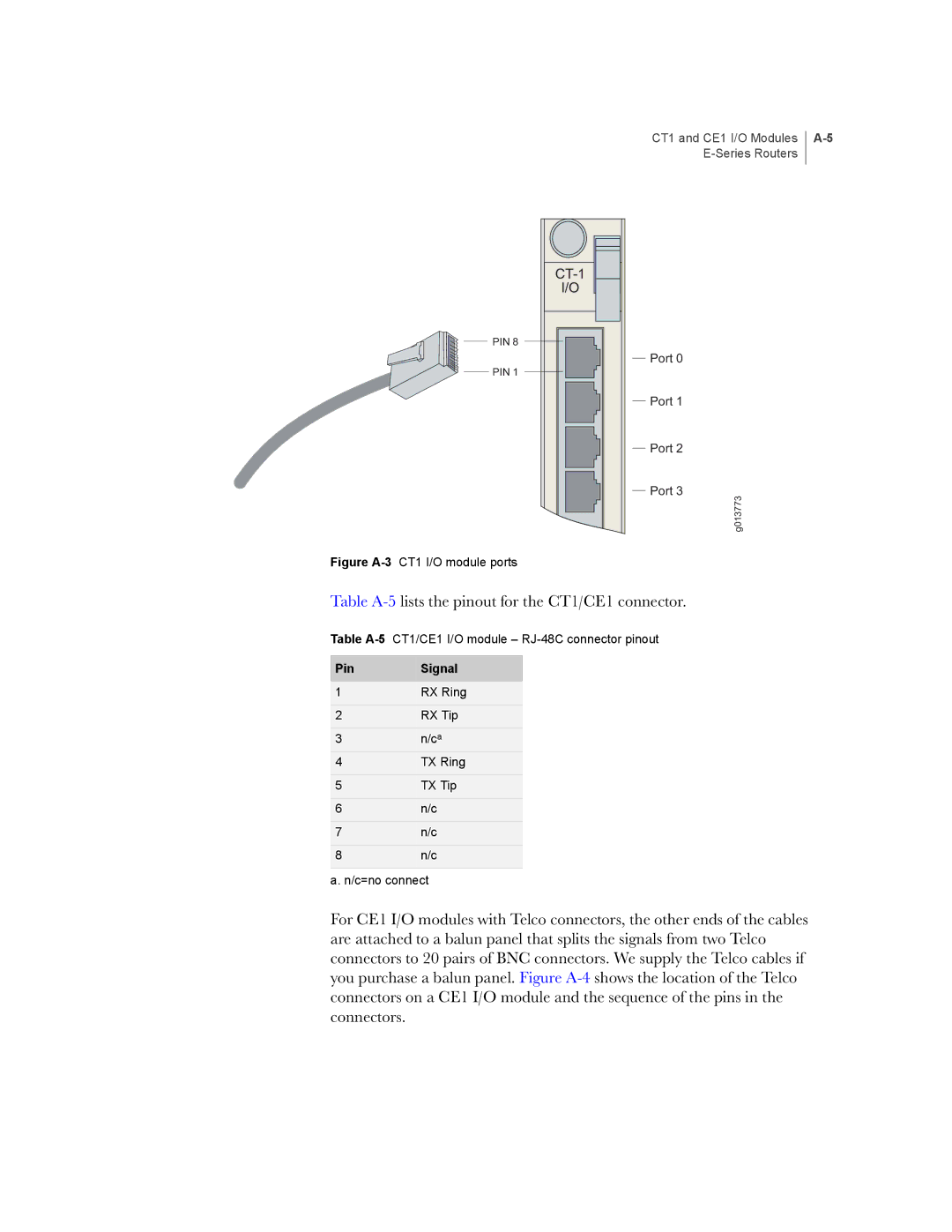
CT1 and CE1 I/O Modules
DB-9 Pin Signal RJ-45 Pin
DB-9 Pin RS-232 Signal Name RJ-45 Pin
Table A-5lists the pinout for the CT1/CE1 connector
CE1
CT1 and CE1 I/O Modules
Pin Signal
Installing JUNOSe Software
Installing Software When a Firewall Exists
System will be unavailable during the installation process
To access this mode via the CLI Issue the enable command
Task 6 Configure Access to the Network Host
To enable the FTP server, use the ftp-server enable command
Task 11 Save the Current Configuration
Installing Software When a Firewall Does Not Exist
System will be unavailable during the installation process
Appendix B
Task 6 Mount the CD on the Network Host
Appendix B
Installing Software in Boot Mode
Task 4 Assign an IP Address
Copying Release Files from One E-Series Router to Another
Upgrading Systems That Are Operating with Two SRP Modules
Host1#copy running-configuration system2.cnf
Appendix B
Contact Information
Customer Support
Information You Need to Supply
Returning Products for Repair or Replacement
Appendix C Customer Support
Declares, that the products Product Name
Declaration of Conformity
Appendix D Declaration of Conformity
Numbers
Index
Index
Series Routers
Online LED
Sync LED
YEL ALM LED