Series Routers Installation and User Guide
FCC Requirements For Consumer Products
Federal Communications Commission FCC Statement
Avis CS-03 d’Industrie Canada
Industry Canada Notice CS-03
C. Explanatory Notes Equipment Attachment Limitations
EC Declaration of Conformity
Software License AGREEMENTa
Page
Page
Page
Contents
Unpacking and Inspecting E-Series Routers
Cabling E-Series Routers
Xii
Powering Up E-Series Routers
Xiii
Part 2. System and Module Specifications
Xiv
Appendix B Installing JUNOSe Software
Series Routers
About This Guide
Icon Meaning Description
Audience
Conventions
Xvi
Xvii
Documentation
Xviii
Xix
Comments About the Documentation
Contacting Customer Support
Part
Installing and Using E-Series Routers
Page
Overview
Series Overview
1E-series router communicating over T1/T3 lines
Where E-Series Routers Fit
CPE
ERX-14xx Models
Cable Management Bracket
ERX-7xx Models
Line module Fan tray SRP module Pcmcia slot
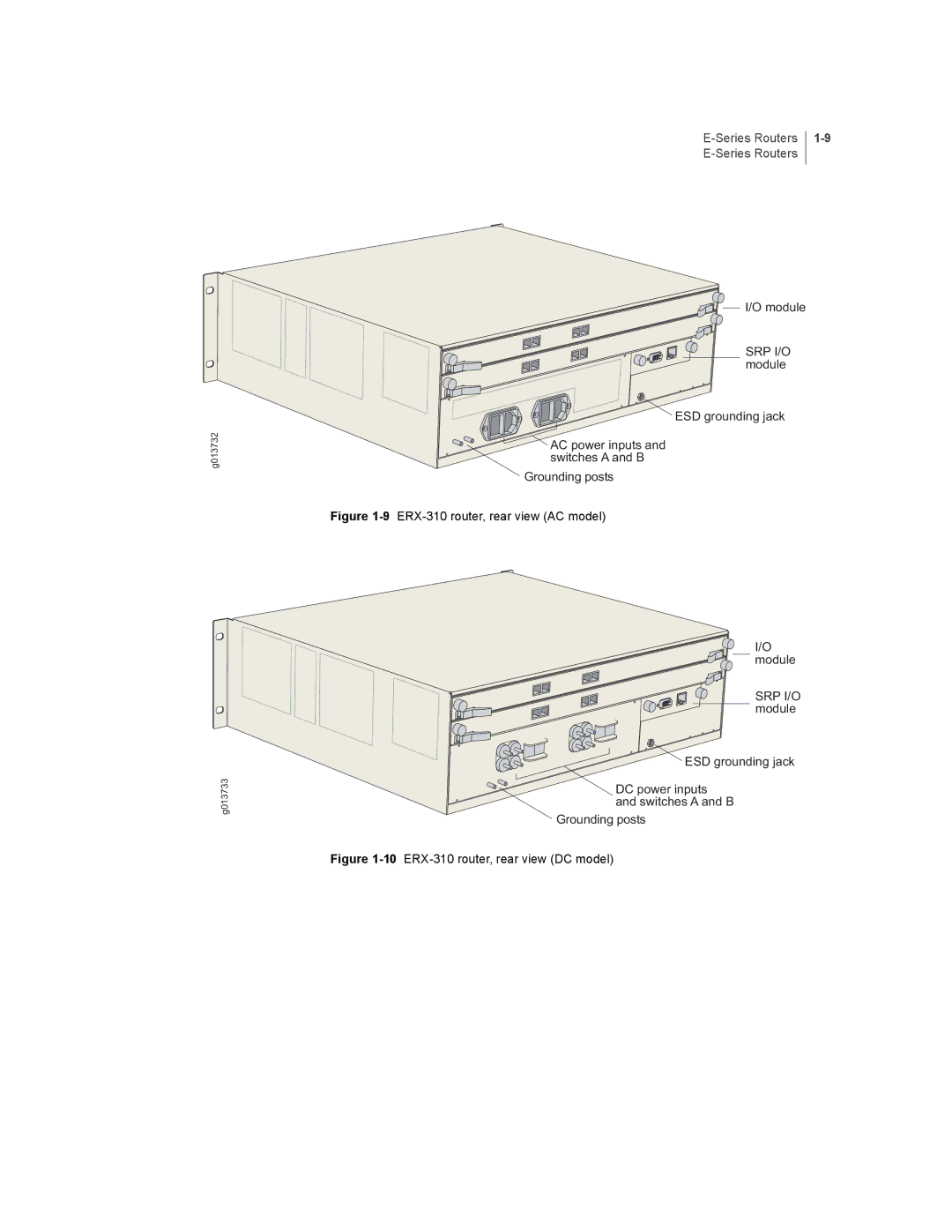
ERX-310 Router
9ERX-310 router, rear view AC model
SRP I/O
Series Modules
SRP Module
Module Details
Modules
Line Modules
Network Management Tools
Redundancy Features
Redundancy Features E-Series Routers
Spare line module Primary line module
Power
Series Overview
Before You Begin
Unpacking Inspecting E-Series Routers
1Removing an L-bracket
Unpacking ERX-14xx Models
Contacting Juniper Networks
Inspecting E-Series Router Components and Accessories
Unpacking ERX-7xx Models and ERX-310 Routers
If You Detect or Suspect Damage
Next Step
Your Preinstallation Responsibilities
Installation Guidelines Requirements
Regulatory Compliances
Environmental Requirements
Safety Guidelines
Equipment Rack Requirements
ERX-310 Power Cord Warnings AC Model
Equipment Rack Requirements Series Routers
Mechanical Requirements
Air output ERX-310 router ERX-7xx model
Cabling Recommendations
Installing E-Series Routers
1ERX-7xx model, rear view
Freestanding Installation
Rack-Mounted Installation
2E-series routers installed in recommended order
Safety Guidelines
Installing the Router
Installing Modules
Slot Groups
Slot Groups for the ERX-1410 Router
Combinations of Line Modules
Series Router Location
Order of Installation
Series Router Slot
Installing SRP I/O and SRP Modules
Installing an SRP I/O Module
Installing SRP I/O and SRP Modules Series Routers
Series Router Module Slot
Installing Line and I/O Modules
Page
Opened
Installing Components for Line Module Redundancy
Installing Modules
Installing the I/O Modules
Configuring Line Module Redundancy
Cabling Overview
Cabling E-Series Routers
Cabling E-Series Routers
Cabling Overview Series Routers
Connection Port and Cable Used
Required Tools, Wires, and Cables
Port Description
Cabling the SRP I/O Module
DB-9
Console Ports
See , Accessing E-Series Routers, for more information about
Cable/Wire From ERX-7xx/14xx models
Cabling the E-Series Router for Power
ERX-310 router
OFF
5, and -6 as needed
Negative leads at the power source
ERX-310 router AC model
7I/O module with BNCs
Cabling I/O Modules
Hssi I/O module uses a standard 50-pin Hssi connector
RJ-45 Connectors
Class 1 LED Product
Modules with SC connectors are defined as follows
Cabling X.21/V.35 Connectors
Turn to , Powering Up E-Series Routers
Before You Power Up the System
Powering Up E-Series Routers
Installation Task
Powering Up
Status LEDs
Powering Down
Chapter
Setting Up Management Access
Accessing E-Series Routers
Console Port Setup
Connecting Directly to the E-Series Router
Telnet Setup
Host1config#line vty 0 Host1config-line#
Snmp
Required Tools and Items
Maintaining E-Series Routers
Storing Modules and Components
Cleaning the System
Upgrading NVS Cards on SRP Modules
Power up the system see , Powering Up E-Series Routers
Page
Replacing an NVS Card
Upgrading Memory on SRP Modules
Locate the four Sodimm sockets on the SRP module see
Verifying the Upgrade
Replacing SFPs on GE I/O Modules
Installing SFPs
6Installing an SFP on an E-series GE I/O module
Host1vr2#show interfaces gigabitEthernet2/0
7Fan tray in ERX-14xx model
Replacing Fan Trays
Removing the Fan Tray
Installing the Fan Tray
10Attaching a cable management bracket
Installing a Cable-Management Bracket on ERX-7xx Models
Diagnosing Problems
Troubleshooting
10-2
Troubleshooting Power Failures
Symptom Possible Problems Actions
Understanding Status LEDs to Troubleshoot
FE-8, GE/FE, HSSI, OCx/STMx, and X.21/V.35 line
10-3
Active
10-5
Ethernet line module Figure Other line modules Figure
Sync
10-6
10-7
Diagnostic Signs Possible Problems Actions
Status Process
Slot slotnumber command
State of the Line Module
Monitoring Temperatures of Modules
Diagnostic Signs Possible Problems
10-9
Double-Bit Errors on SRP Modules
Resetting Line Modules and SRP Modules
Cause of High Operating Temperature Symptoms Resolution
Occurred
10-11
10-12
System and Module Specifications
Page
ERX-14xx Models Specifications
System Specifications
Electromagnetic Emissions
11-3
ERX-7xx Models Specifications
, Installation Guidelines and Requirements
11-5
ERX-310 Router Specifications
Category Specification Weight DC model
Weight AC model
11-6
11-7
Category Specification Telecommunications Certification
11-8
Module Functionality
Module Specifications
COC3/STM1
CE1
Name Description Capability
Release Information
COC12/STM4
CT1
Hssi
IPSec Service
OC3/STM1
12-7
OC3/STM1 POS
OC12/STM4 ATM
OC12/STM4 POS
SRPs
OC48/STM16
SRP-10G
21/V.35
TSM
12-13
Module Specifications
SRP-SE10G HSSI-3F
12-15
Model SRP Module No.
Mode SRP-SE10G
Type Compatibility
Connector Type Cabling Specifications
Model SRP Module
Connector Type Cabling Specifications COC12/STM4
ERX-14xx models SRP-10G Min -5.0 dBm
SRP-5G BNC
BT43 SMB
12-22CHAPTER 12 Module Specifications
Module Specifications 12-23E-Series Routers
HSSI-3
4XOC3 Asic
12-26CHAPTER 12 Module Specifications
Module Specifications 12-27E-Series Routers
12-28CHAPTER 12 Module Specifications
OC12/STM4
12-30CHAPTER 12 Module Specifications
Module Specifications 12-31E-Series Routers
12-32CHAPTER 12 Module Specifications
Module Specifications 12-33E-Series Routers
Connector Type Cabling Specifications OC48/STM16
Model SRP Module No. Module Label a Type Compatibility
SRP-5G+ BNC
SRP-5G+ BT43 SMB
Connector Type Cabling Specifications 21/V.35
Speed Hz Feet
12-39
12-40
Module
Protocol Support
13-2
Channelized OCx/STMx Modules
Protocol or Application
RIP
Channelized T1 and E1 Modules
13-4
Channelized T3 Modules
CT3/T3-F0 Line
13-5
Application
Ethernet Modules
13-6
FE-2 Line Module GE/FE Line Protocol or
13-7
Hssi Modules
HSSI-3F Line Modules with
13-8
13-9
OCx/STMx ATM Modules
OCx/STMx ATM Line Protocol or
13-10
OCx/STMx POS and OC48 Modules
OCx/STMx POS
ATM Ospf
Service Line IPSec Service Application
Tunnel Service Modules
13-12
13-13
Unchannelized E3 Modules
13-14
13-15
Unchannelized T3 Modules
13-16CHAPTER 13 Protocol Support
13-17
21/V.35 Modules
21/V.35-16
13-18
Appendixes
Page
SRP I/O Module
Cable Pinouts
Figure A-1SRP I/O module serial port
Pin Signal
SRP I/O Module E-Series Routers
DB-9 Pin RS-232 Signal Name RJ-45 Pin
DB-9 Pin Signal RJ-45 Pin
CT1 and CE1 I/O Modules
Table A-5lists the pinout for the CT1/CE1 connector
CE1
CT1 and CE1 I/O Modules
Pin Signal
Installing JUNOSe Software
Installing Software When a Firewall Exists
System will be unavailable during the installation process
To access this mode via the CLI Issue the enable command
Task 6 Configure Access to the Network Host
To enable the FTP server, use the ftp-server enable command
Task 11 Save the Current Configuration
Installing Software When a Firewall Does Not Exist
System will be unavailable during the installation process
Appendix B
Task 6 Mount the CD on the Network Host
Appendix B
Installing Software in Boot Mode
Task 4 Assign an IP Address
Copying Release Files from One E-Series Router to Another
Upgrading Systems That Are Operating with Two SRP Modules
Host1#copy running-configuration system2.cnf
Appendix B
Contact Information
Customer Support
Information You Need to Supply
Returning Products for Repair or Replacement
Appendix C Customer Support
Declares, that the products Product Name
Declaration of Conformity
Appendix D Declaration of Conformity
Numbers
Index
Index
Series Routers
Online LED
Sync LED
YEL ALM LED