Understanding Status LEDs to Troubleshoot
10-7
LED Activity During Booting
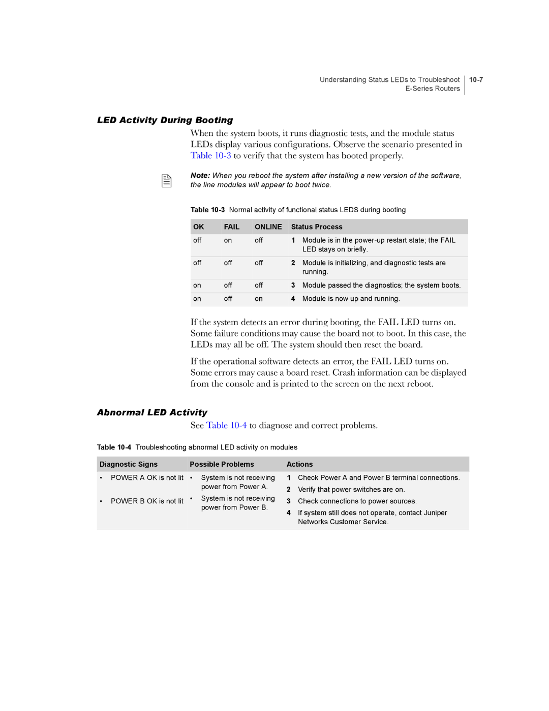
When the system boots, it runs diagnostic tests, and the module status
LEDs display various configurations. Observe the scenario presented in
Table
Note: When you reboot the system after installing a new version of the software, the line modules will appear to boot twice.
Table
OK | FAIL | ONLINE | Status Process | |
off | on | off | 1 | Module is in the |
|
|
|
| LED stays on briefly. |
off | off | off | 2 | Module is initializing, and diagnostic tests are |
|
|
|
| running. |
on | off | off | 3 | Module passed the diagnostics; the system boots. |
on | off | on | 4 | Module is now up and running. |
|
|
|
|
|
If the system detects an error during booting, the FAIL LED turns on.
Some failure conditions may cause the board not to boot. In this case, the
LEDs may all be off. The system should then reset the board.
If the operational software detects an error, the FAIL LED turns on. Some errors may cause a board reset. Crash information can be displayed from the console and is printed to the screen on the next reboot.
Abnormal LED Activity
See Table 10-4 to diagnose and correct problems.
Table
Diagnostic Signs | Possible Problems | Actions | |
• POWER A OK is not lit | • System is not receiving | 1 | Check Power A and Power B terminal connections. |
| power from Power A. | 2 | Verify that power switches are on. |
| • System is not receiving | ||
• POWER B OK is not lit | 3 | Check connections to power sources. | |
| power from Power B. | 4 | If system still does not operate, contact Juniper |
|
| ||
Networks Customer Service.
