Understanding Status LEDs to Troubleshoot
10-3
LED Activity During Booting
When the system boots, it runs a series of tests for each module installed in the system, and the LEDs display various configurations. Refer to the tables in this section to understand normal and abnormal LED activity. For troubleshooting information, see Table
LED Identification
The system’s modules have two sets of status LEDs. The top set indicates generic router and module status. The bottom set indicates
The number against the port status LED on a line module corresponds to the number of the port on the I/O module. Some line modules have more port status LEDs than the number of ports on the I/O module. In these cases, only the LEDs for the corresponding ports on the I/O modules are active.
For example, an OCx/STMx line module can pair with either an
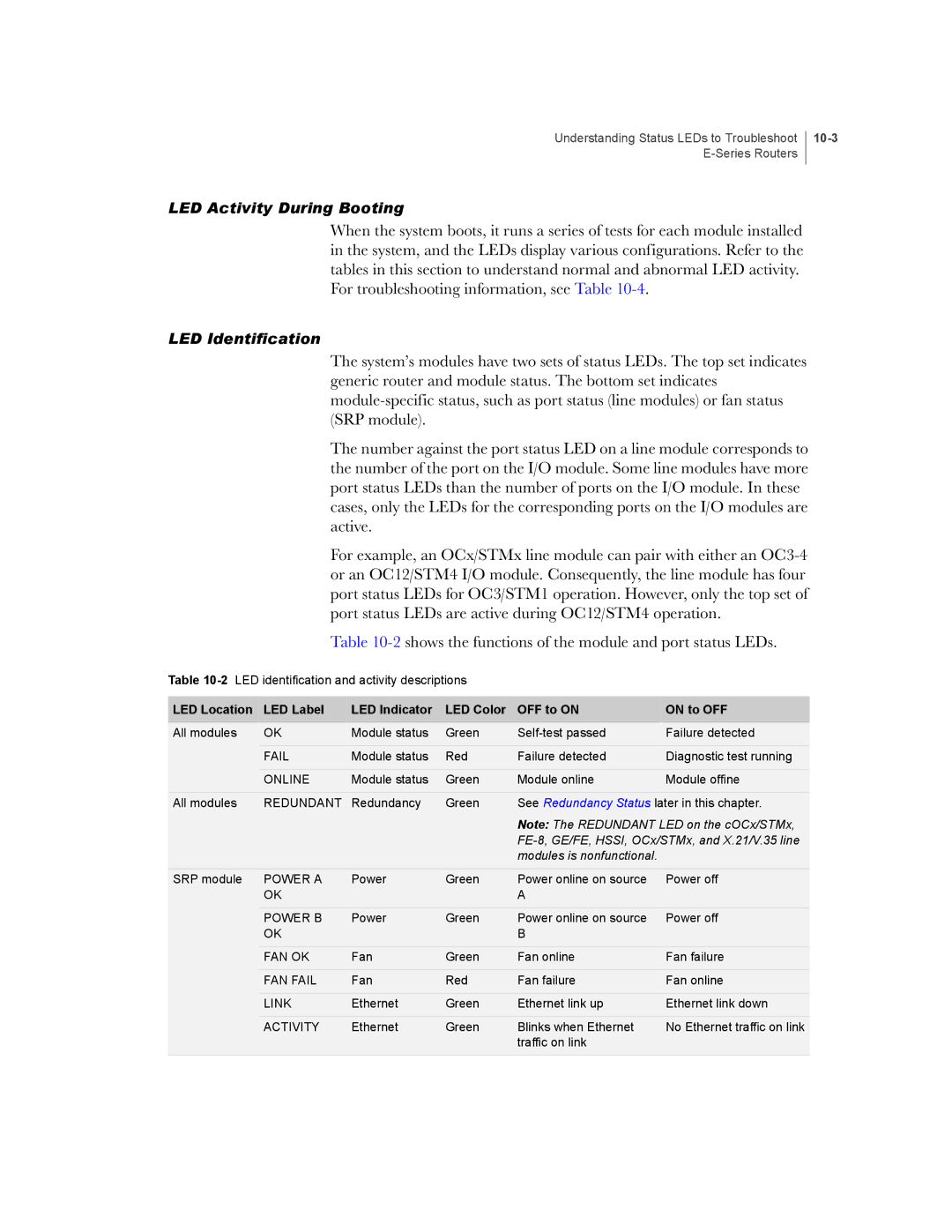
Table
Table
LED Location | LED Label | LED Indicator | LED Color | OFF to ON | ON to OFF |
All modules | OK | Module status | Green | Failure detected | |
|
|
|
|
|
|
| FAIL | Module status | Red | Failure detected | Diagnostic test running |
|
|
|
|
|
|
| ONLINE | Module status | Green | Module online | Module offine |
|
|
|
|
| |
All modules | REDUNDANT | Redundancy | Green | See Redundancy Status later in this chapter. | |
|
|
|
| Note: The REDUNDANT LED on the cOCx/STMx, | |
|
|
|
|
| |
|
|
|
| modules is nonfunctional. |
|
SRP module | POWER A | Power | Green | Power online on source | Power off |
| OK |
|
| A |
|
| POWER B | Power | Green | Power online on source | Power off |
| OK |
|
| B |
|
| FAN OK | Fan | Green | Fan online | Fan failure |
|
|
|
|
|
|
| FAN FAIL | Fan | Red | Fan failure | Fan online |
|
|
|
|
|
|
| LINK | Ethernet | Green | Ethernet link up | Ethernet link down |
|
|
|
|
|
|
| ACTIVITY | Ethernet | Green | Blinks when Ethernet | No Ethernet traffic on link |
|
|
|
| traffic on link |
|
|
|
|
|
|
|