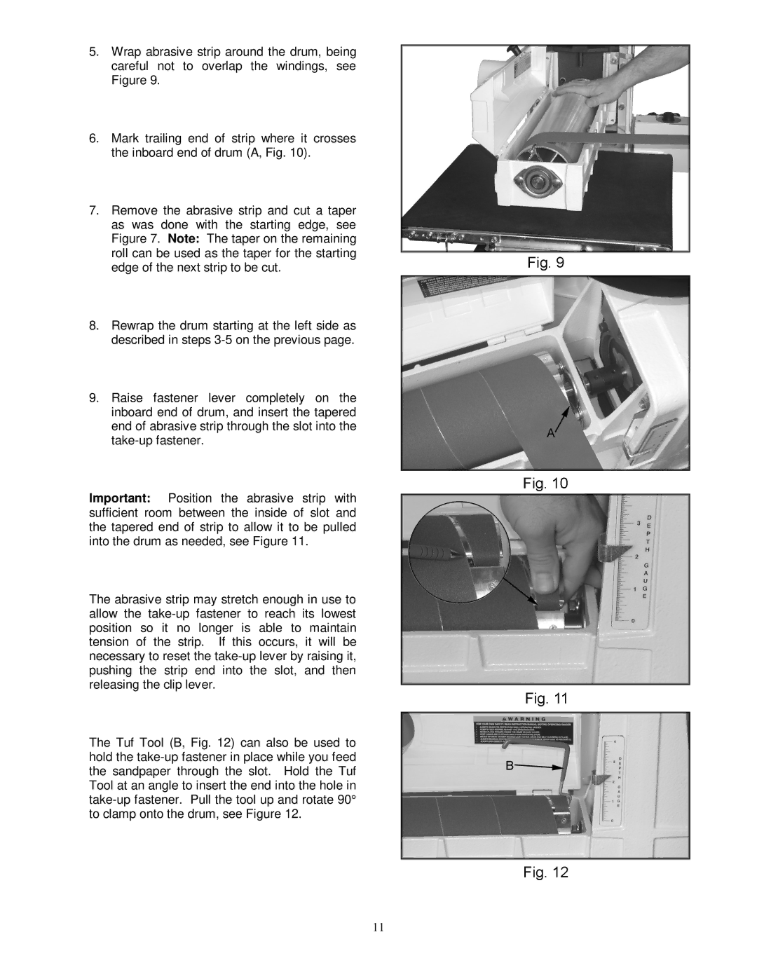
5.Wrap abrasive strip around the drum, being careful not to overlap the windings, see Figure 9.
6.Mark trailing end of strip where it crosses the inboard end of drum (A, Fig. 10).
7.Remove the abrasive strip and cut a taper as was done with the starting edge, see Figure 7. Note: The taper on the remaining roll can be used as the taper for the starting edge of the next strip to be cut.
8.Rewrap the drum starting at the left side as described in steps
9.Raise fastener lever completely on the inboard end of drum, and insert the tapered end of abrasive strip through the slot into the
Important: Position the abrasive strip with sufficient room between the inside of slot and the tapered end of strip to allow it to be pulled into the drum as needed, see Figure 11.
The abrasive strip may stretch enough in use to allow the
The Tuf Tool (B, Fig. 12) can also be used to hold the
11