3.Inspect the camlock studs. Make sure they have not become cracked or broken during transit. Clean all parts thoroughly with solvent. Also clean the spindle and camlocks.
4.Cover all chuck jaws and scroll inside the chuck with #2 lithium tube grease. Cover the spindle, camlocks, and chuck body with a light film of 20W oil.
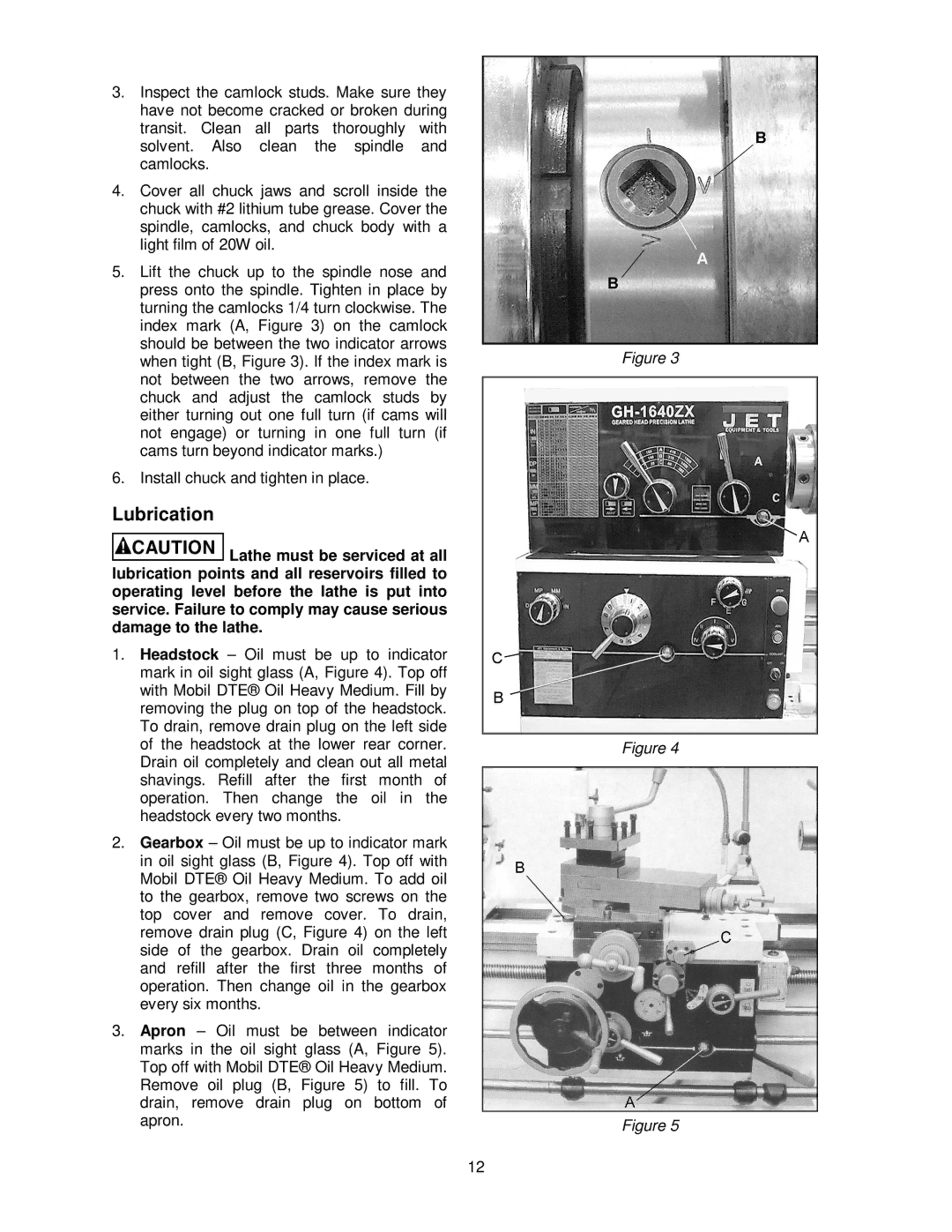
5.Lift the chuck up to the spindle nose and press onto the spindle. Tighten in place by turning the camlocks 1/4 turn clockwise. The index mark (A, Figure 3) on the camlock should be between the two indicator arrows when tight (B, Figure 3). If the index mark is not between the two arrows, remove the chuck and adjust the camlock studs by either turning out one full turn (if cams will not engage) or turning in one full turn (if cams turn beyond indicator marks.)
6.Install chuck and tighten in place.
Lubrication
![]() Lathe must be serviced at all lubrication points and all reservoirs filled to operating level before the lathe is put into service. Failure to comply may cause serious damage to the lathe.
Lathe must be serviced at all lubrication points and all reservoirs filled to operating level before the lathe is put into service. Failure to comply may cause serious damage to the lathe.
1.Headstock – Oil must be up to indicator mark in oil sight glass (A, Figure 4). Top off with Mobil DTE® Oil Heavy Medium. Fill by removing the plug on top of the headstock. To drain, remove drain plug on the left side of the headstock at the lower rear corner. Drain oil completely and clean out all metal shavings. Refill after the first month of operation. Then change the oil in the headstock every two months.
2.Gearbox – Oil must be up to indicator mark in oil sight glass (B, Figure 4). Top off with Mobil DTE® Oil Heavy Medium. To add oil to the gearbox, remove two screws on the top cover and remove cover. To drain, remove drain plug (C, Figure 4) on the left side of the gearbox. Drain oil completely and refill after the first three months of operation. Then change oil in the gearbox every six months.
3.Apron – Oil must be between indicator marks in the oil sight glass (A, Figure 5). Top off with Mobil DTE® Oil Heavy Medium. Remove oil plug (B, Figure 5) to fill. To drain, remove drain plug on bottom of apron.
12
Figure 3
Figure 4
Figure 5
