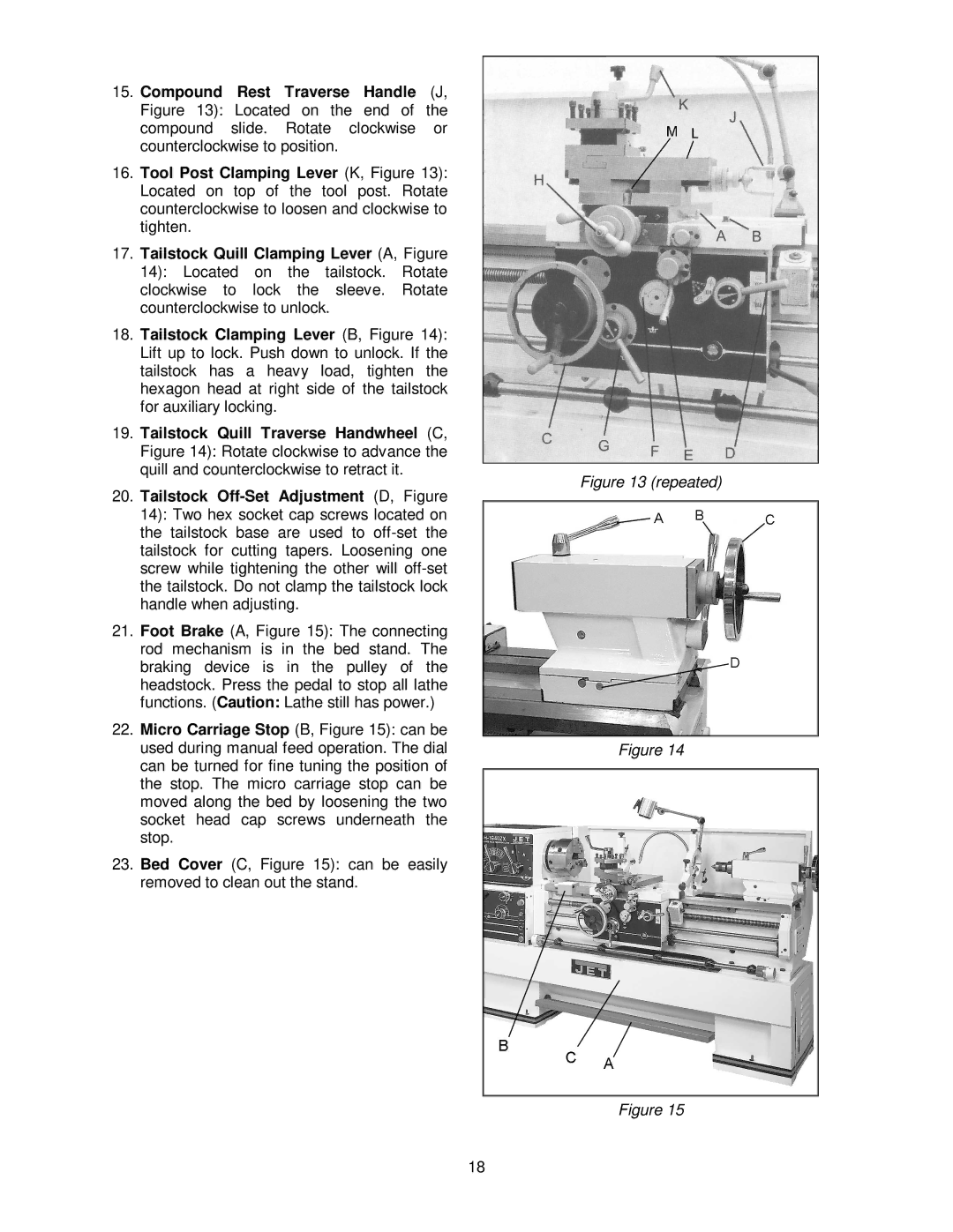
15.Compound Rest Traverse Handle (J, Figure 13): Located on the end of the compound slide. Rotate clockwise or counterclockwise to position.
16.Tool Post Clamping Lever (K, Figure 13): Located on top of the tool post. Rotate counterclockwise to loosen and clockwise to tighten.
17.Tailstock Quill Clamping Lever (A, Figure 14): Located on the tailstock. Rotate clockwise to lock the sleeve. Rotate counterclockwise to unlock.
18.Tailstock Clamping Lever (B, Figure 14): Lift up to lock. Push down to unlock. If the tailstock has a heavy load, tighten the hexagon head at right side of the tailstock for auxiliary locking.
19.Tailstock Quill Traverse Handwheel (C, Figure 14): Rotate clockwise to advance the quill and counterclockwise to retract it.
20.Tailstock
21.Foot Brake (A, Figure 15): The connecting rod mechanism is in the bed stand. The braking device is in the pulley of the headstock. Press the pedal to stop all lathe functions. (Caution: Lathe still has power.)
22.Micro Carriage Stop (B, Figure 15): can be used during manual feed operation. The dial can be turned for fine tuning the position of the stop. The micro carriage stop can be moved along the bed by loosening the two socket head cap screws underneath the stop.
23.Bed Cover (C, Figure 15): can be easily removed to clean out the stand.
18
Figure 13 (repeated)
Figure 14
Figure 15
