./
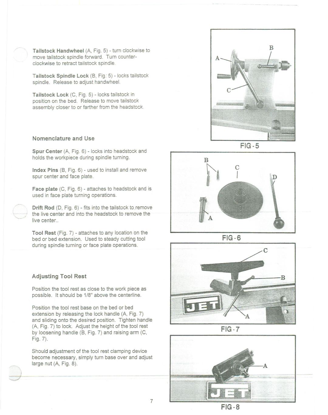
Tailstock Handwheel (A, Fig. 5) - turn clockwise to move tailstock spindle forward. Turn counter- clockwise to retract tailstock spindle.
Tailstock Spindle Lock (B, Fig: 5) - locks tailstock spindle. Release to adjust handwheel.
Tailstock Lock (C, Fig. 5) - locks tailstock in position on the bed. Release to move tailstock assembly closer to or farther from the headstock.
Nomenclature and Use
Spur Center (A, Fig. 6) - locks into headstock and holds the workpiece during spindle turning.
Index Pins (B, Fig. 6) - used to install and remove spur center and face plate.
Face plate (C, Fig. 6) - attaches to headstock and is used in face plate turning operations.
\I the live center and into the headstock to remove the
'/ live center..
Tool Rest (Fig. 7) - attaches to any location on the bed or bed extension. Used to steady cutting tool during spindle turning or face plate operations.
Adjusting Tool Rest
Position the tool rest as close to the work piece as possible. It should be 1/8" above the centerline.
Position the tool rest base on the bed or bed extension by releasing the lock handle (A, Fig. 7) and sliding onto the desired position. Tighten handle (A, Fig. 7) to lock. Adjust the height of the tool rest by loosening handle (B, Fig. 7) and raising ,arm (C, Fig. 7).
Should adjustment of the tool rest clamping device become necessary, simply turn base over and adjust
B
c
fl I
fA
FIG-6
B
FIG-?
d-
7
FIG.8