|
|
|
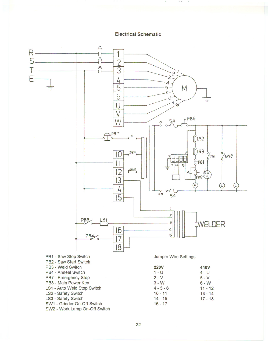
| Electrical Schematic |
|
|
| ||
R |
| A |
|
|
|
|
|
| |
| A | 1 |
|
|
|
|
| ||
S |
| 2 |
|
|
|
|
| ||
| it |
|
|
|
|
|
| ||
T |
| A | 3 |
|
| ~ |
| ||
|
|
|
|
|
| ||||
E | l - |
|
| 4 |
|
| |||
|
|
| 6 |
|
| ||||
|
|
| 5 |
| ? |
|
| ||
|
|
|
|
|
|
| b |
|
|
|
|
|
| U |
|
| |||
|
|
|
| V |
|
|
| ||
|
|
|
| w |
|
| SA | ...r:F'BB | |
|
|
|
|
|
| 0 | |||
|
|
| ~~B7 | .0 |
|
| II fLS2I | ||
|
|
|
| IO'~O |
|
|
| 31 ~LS3 | |
|
|
|
| II |
|
|
| 7i88881 | |
|
|
|
| f21 | AbO |
|
|
|
|
|
|
|
| 13 |
|
|
|
|
|
|
|
|
| 14 |
| 110 |
|
| |
|
|
|
|
|
| 5A |
| ||
|
|
|
| 15 |
|
|
|
| |
|
|
|
|
|
|
|
|
| |
|
| PB3/ | LS I |
|
|
|
|
| ,WELDER |
|
| 0 | 16 |
|
|
|
| ||
|
| PB4 |
|
|
|
|
|
| |
|
|
| 17 |
|
|
|
|
| |
|
|
|
|
|
|
|
|
| |
|
|
|
| 18 |
|
|
|
|
|
| PB1 - Saw Stop Switch |
|
|
| Jumper Wire Settings | ||||
| P82 - Saw Start Switch |
|
|
|
|
|
|
| |
| PB3 - Weld Switch |
|
|
| 220V |
| 440V | ||
| PB4 - Anneal | Switch |
|
|
|
|
| ||
| PB7 - Emergency Stop |
|
|
|
|
| 5 - V | ||
| PB8 - Main Power Key |
|
|
|
| ||||
| LS1 - Auto Weld Stop Switch |
|
|
| 11 - 12 | ||||
| LS2 - Safety | Switch |
|
|
|
| 13 - 14 | ||
| LS3 - Safety | Switch |
|
|
| 14 - 15 |
| 17 - 18 | |
| SW1 - Grinder |
|
| 16 - 17 |
|
| |||
SW2 - Work Lamp
22