|
|
|
|
|
| ! |
|
| IMPORTANT |
|
|
|
|
|
|
|
|
|
| ||||||||||
2) Signal Sensing | You cannot use the |
|
|
|
| ||||||||||||||||||||||||
The 500/1v2 can be turned on and off using |
| The amplifier will operate with only one input | |||||||||||||||||||||||||||
two different methods: |
| feature of the 500/1v2 is its ability to be turned | processors that are in the signal path before the | connection (left or right), but will require an | |||||||||||||||||||||||||
|
|
|
| on and off by the presence or lack of signal at | 500/1v2. (Signal will not pass through most | increase in input sensitivity to overcome the loss | |||||||||||||||||||||||
1) A conventional +12V remote |
| its audio inputs. This allows you to operate the | processors when they are not powered up, | of signal. If a mono input signal is to be run, we | |||||||||||||||||||||||||
2) A signal sensing |
| amplifier without having to locate a remote | meaning that the amplifier will not turn on | recommend that you use a | |||||||||||||||||||||||||
|
|
|
| until that processor is active). |
|
|
| JL Audio ECS model | |||||||||||||||||||||
|
|
|
| very useful if interfacing the amplifier with |
|
|
|
|
|
|
|
|
|
|
|
|
|
|
|
|
|
|
| the mono signal into both inputs of the amplifier. | |||||
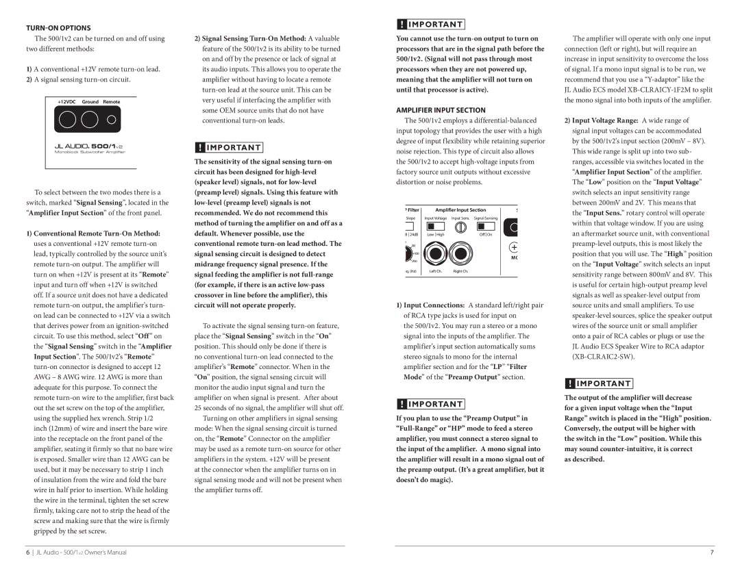
| +12VDC Ground Remote |
|
|
|
|
|
|
|
|
|
|
|
|
|
|
|
|
|
|
| |||||||||
|
|
|
| some OEM source units that do not have | AMPLIFIER Input Section |
|
|
|
|
|
|
| |||||||||||||||||
|
|
|
| conventional |
| The 500/1v2 employs a | 2) Input Voltage Range: A wide range of | ||||||||||||||||||||||
|
|
|
|
|
|
| input topology that provides the user with a high |
| signal input voltages can be accommodated | ||||||||||||||||||||
|
|
|
|
|
|
| degree of input flexibility while retaining superior |
| by the 500/1v2’s input section (200mV – 8V). | ||||||||||||||||||||
| 500/1v2 |
| ! | IMPORTANT |
|
| |||||||||||||||||||||||
|
|
| noise rejection. This type of circuit also allows |
| This wide range is split up into two sub- | ||||||||||||||||||||||||
| Monoblock Subwoofer Amplifier |
|
|
| |||||||||||||||||||||||||
| The sensitivity of the signal sensing |
| |||||||||||||||||||||||||||
|
|
| the 500/1v2 to accept |
| ranges, accessible via switches located in the | ||||||||||||||||||||||||
|
|
| circuit has been designed for | factory source unit outputs without excessive |
| “Amplifier Input Section” of the amplifier. | |||||||||||||||||||||||
|
|
|
| ||||||||||||||||||||||||||
|
|
| (speaker level) signals, not for | distortion or noise problems. |
|
|
|
| The “Low” position on the “Input Voltage” | ||||||||||||||||||||
To select between the two modes there is a | (preamp level) signals. Using this feature with |
|
|
|
|
|
|
|
|
|
|
|
|
|
|
|
|
|
|
|
| switch selects an input sensitivity range | |||||||
switch, marked “Signal Sensing”, located in the |
|
|
|
|
|
|
|
|
|
|
|
|
|
|
|
|
|
|
|
| between 200mV and 2V. This means that | ||||||||
“Amplifier Input Section” of the front panel. | recommended. We do not recommend this |
|
| P Filter |
|
|
| Amplifier Input Section |
| S |
| the “Input Sens.” rotary control will operate | |||||||||||||||||
|
|
|
|
| |||||||||||||||||||||||||
|
| Slope |
| Input Voltage | Input Sens. Signal Sensing |
|
|
|
| ||||||||||||||||||||
|
|
| method of turning the amplifier on and off as a |
|
|
|
|
|
|
| within that voltage window. If you are using | ||||||||||||||||||
|
|
|
|
|
|
|
|
|
|
|
|
|
|
|
|
|
|
|
|
|
|
| |||||||
|
|
|
|
|
|
|
|
|
|
|
|
|
|
|
|
|
|
|
|
|
| ||||||||
1) Conventional Remote | default. Whenever possible, use the |
|
|
|
|
|
|
|
|
|
|
|
|
|
|
|
|
|
|
| an aftermarket source unit, with conventional | ||||||||
|
| B 24dB |
|
| Low High |
|
| Off On |
|
|
| ||||||||||||||||||
uses a conventional +12V remote | conventional remote | 80 |
|
|
|
|
|
|
|
|
|
|
|
|
| ||||||||||||||
|
|
|
|
|
|
| 5 |
|
|
|
|
|
|
|
|
|
|
|
|
|
|
|
|
|
|
|
| ||
lead, typically controlled by the source unit’s | signal sensing circuit is designed to detect |
|
|
|
|
|
| 100 |
|
|
|
|
|
|
|
|
|
| MO |
| position that you will use. The “High” position | ||||||||
remote | midrange frequency signal presence. If the | 200 |
|
|
|
|
|
|
|
|
|
|
|
|
| on the “Input Voltage” switch selects an input | |||||||||||||
turn on when +12V is present at its “Remote” | signal feeding the amplifier is not |
|
| eq. (Hz) |
|
| Left Ch. | Right Ch. |
|
|
|
| sensitivity range between 800mV and 8V. This | ||||||||||||||||
|
|
|
|
|
|
|
|
|
|
|
|
|
|
|
|
|
|
|
| ||||||||||
input and turn off when +12V is switched | (for example, if there is an active |
|
|
|
|
|
|
|
|
|
|
|
|
|
|
|
|
|
|
|
| is useful for certain | |||||||
off. If a source unit does not have a dedicated | crossover in line before the amplifier), this |
|
|
|
|
|
|
|
|
|
|
|
|
|
|
|
|
|
|
|
| signals as well as | |||||||
remote | circuit will not operate properly. | 1) Input Connections: A standard left/right pair |
| source units and small amplifiers. To use | |||||||||||||||||||||||||
on lead can be connected to +12V via a switch |
|
|
|
|
| of RCA type jacks is used for input on |
| ||||||||||||||||||||||
that derives power from an |
| To activate the signal sensing |
| the 500/1v2. You may run a stereo or a mono |
| wires of the source unit or small amplifier | |||||||||||||||||||||||
circuit. To use this method, select “Off” on | place the “Signal Sensing” switch in the “On” |
| signal into the inputs of the amplifier. The |
| onto a pair of RCA cables or plugs or use the | ||||||||||||||||||||||||
the “Signal Sensing” switch in the “Amplifier | position. This should only be done if there is |
| amplifier’s input section automatically sums |
| JL Audio ECS Speaker Wire to RCA adaptor | ||||||||||||||||||||||||
Input Section”. The 500/1v2’s “Remote” | no conventional |
| stereo signals to mono for the internal |
| |||||||||||||||||||||||||
amplifier’s “Remote” connector. When in the |
| amplifier section and for the “LP” “Filter |
|
|
|
| |||||||||||||||||||||||
AWG – 8 AWG wire. 12 AWG is more than | “On” position, the signal sensing circuit will |
| Mode” of the “Preamp Output” section. |
|
|
|
| ||||||||||||||||||||||
|
| ! | IMPORTANT |
| |||||||||||||||||||||||||
adequate for this purpose. To connect the | monitor the audio input signal and turn the |
|
|
|
|
|
|
|
|
|
|
|
|
|
|
|
|
|
|
|
|
| |||||||
|
|
|
|
|
|
|
|
|
|
|
|
|
|
|
|
|
|
| The output of the amplifier will decrease | ||||||||||
remote | amplifier on when signal is present. After about |
|
|
|
|
|
|
|
|
|
|
|
|
|
|
|
|
|
|
| |||||||||
|
|
| ! | IMPORTANT |
|
|
|
|
|
| |||||||||||||||||||
out the set screw on the top of the amplifier, | 25 seconds of no signal, the amplifier will shut off. |
|
|
|
|
|
| for a given input voltage when the “Input | |||||||||||||||||||||
|
|
|
|
|
|
|
|
|
|
|
|
|
|
|
|
|
|
| |||||||||||
using the supplied hex wrench. Strip 1/2 |
| Turning on other amplifiers in signal sensing | If you plan to use the “Preamp Output” in | Range” switch is placed in the “High” position. | |||||||||||||||||||||||||
inch (12mm) of wire and insert the bare wire | mode: When the signal sensing circuit is turned |
| Conversely, the output will be higher with | ||||||||||||||||||||||||||
into the receptacle on the front panel of the | on, the “Remote” Connector on the amplifier | amplifier, you must connect a stereo signal to | the switch in the “Low” position. While this | ||||||||||||||||||||||||||
amplifier, seating it firmly so that no bare wire | may be used as a remote | the input of the amplifier. A mono signal into | may sound | ||||||||||||||||||||||||||
is exposed. Smaller wire than 12 AWG can be | amplifiers in the system. +12V will be present | the amplifier will result in a mono signal out of | as described. | ||||||||||||||||||||||||||
used, but it may be necessary to strip 1 inch | at the connector when the amplifier turns on in | the preamp output. (It’s a great amplifier, but it |
|
|
|
| |||||||||||||||||||||||
of insulation from the wire and fold the bare | signal sensing mode and will not be present when | doesn’t do magic). |
|
|
|
|
|
|
| ||||||||||||||||||||
wire in half prior to insertion. While holding | the amplifier turns off. |
|
|
|
|
|
|
|
|
|
|
|
|
|
|
|
|
|
|
|
|
|
|
| |||||
the wire in the terminal, tighten the set screw |
|
|
|
|
|
|
|
|
|
|
|
|
|
|
|
|
|
|
|
|
|
|
|
|
|
|
| ||
firmly, taking care not to strip the head of the screw and making sure that the wire is firmly gripped by the set screw.
6 JL Audio - 500/1v2 Owner’s Manual | 7 |