Appendix A:
Input Sensitivity Level Setting
JL Audio amplifiers utilizing the Regulated
Intelligent Power Supply (R.I.P.S.) allow delivery of their rated power when connected to any load impedance from 1.5 - 4Ω per channel and when connected to a charging system with any voltage from 11 - 14.5V. This design is beneficial for many reasons. One of these reasons is ease of setup. Because each JL Audio amplifier will always deliver the same amount of power within its operational range of impedances and supply voltages, the maximum, unclipped output is very predictable.
This makes setting the gain structure via the input sensitivity controls very simple. Following the directions below will allow the user to adjust the input sensitivity of the amplifier(s) simply and easily in just a few minutes using equipment which is commonly available in installation bays.
Necessary Equipment
•Digital AC Voltmeter
•CD with a
0 dB reference level in the frequency range to be amplified for that set of channels
(50 Hz for subwoofer channels, 1 kHz for a midrange application). The CleanSweep®
Calibration Disc contains the appropriate test tones and is available for sale at http://store.jlaudio.com Do not use attenuated test tones
The Nine-Step Procedure
1) Disconnect the speaker(s) from the | |
| amplifier’s speaker output connectors. |
2) | Turn off all processing (bass/treble, loudness, |
| EQ, etc.) on the source unit, processors (if |
| used) and amplifier. Set fader control to center |
| position and subwoofer level control to 3/4 of |
| maximum (if used to feed the 500/1v2). |
3) | Switch the “Input Voltage” switch to “Low” |
| and turn the “Input Sens.” control all the |
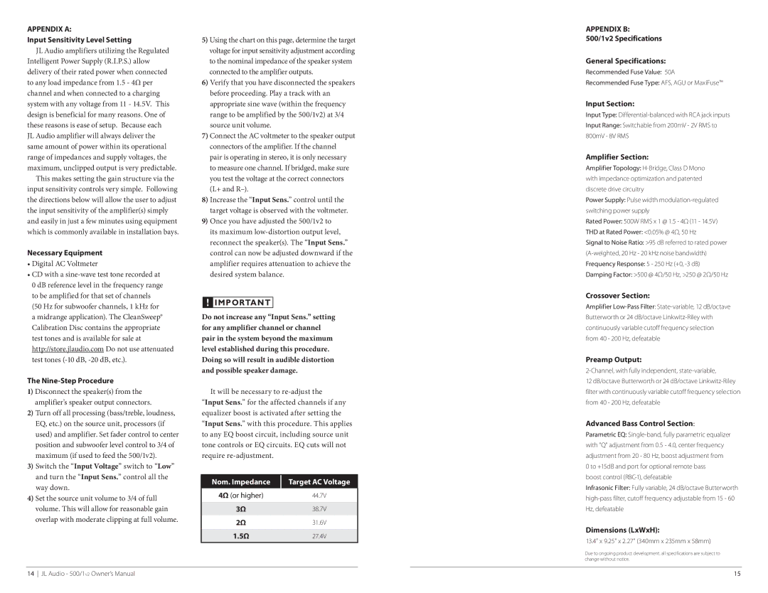
5)Using the chart on this page, determine the target voltage for input sensitivity adjustment according to the nominal impedance of the speaker system connected to the amplifier outputs.
6)Verify that you have disconnected the speakers before proceeding. Play a track with an appropriate sine wave (within the frequency range to be amplified by the 500/1v2) at 3/4 source unit volume.
7)Connect the AC voltmeter to the speaker output connectors of the amplifier. If the channel pair is operating in stereo, it is only necessary to measure one channel. If bridged, make sure you test the voltage at the correct connectors (L+ and
8)Increase the “Input Sens.” control until the target voltage is observed with the voltmeter.
9)Once you have adjusted the 500/1v2 to its maximum
!![]() IMPORTANT
IMPORTANT
Do not increase any “Input Sens.” setting for any amplifier channel or channel pair in the system beyond the maximum level established during this procedure. Doing so will result in audible distortion and possible speaker damage.
It will be necessary to
“Input Sens.” with this procedure. This applies to any EQ boost circuit, including source unit tone controls or EQ circuits. EQ cuts will not require
Appendix B:
500/1v2 Specifications
General Specifications:
Recommended Fuse Value: 50A
Recommended Fuse Type: AFS, AGU or MaxiFuse™
Input Section:
Input Type:
Input Range: Switchable from 200mV - 2V RMS to 800mV - 8V RMS
Amplifier Section:
Amplifier Topology:
Power Supply: Pulse width
Rated Power: 500W RMS x 1 @ 1.5 - 4Ω (11 - 14.5V)
THD at Rated Power: <0.05% @ 4Ω, 50 Hz
Signal to Noise Ratio: >95 dB referred to rated power
Crossover Section:
Amplifier
Preamp Output:
2-Channel, with fully independent, state-variable,
12 dB/octave Butterworth or 24 dB/octave
Advanced Bass Control Section:
Parametric EQ:
boost control
way down. |
4) Set the source unit volume to 3/4 of full |
volume. This will allow for reasonable gain |
overlap with moderate clipping at full volume. |
Nom. Impedance
4Ω (or higher)
3Ω
2Ω
1.5Ω
Target AC Voltage
44.7V
38.7V
31.6V
27.4V
Infrasonic Filter: Fully variable, 24 dB/octave Butterworth
Dimensions (LxWxH):
13.4" x 9.25" x 2.27" (340mm x 235mm x 58mm)
Due to ongoing product development, all specifications are subject to change without notice.
14 JL Audio - 500/1v2 Owner’s Manual
15