Appendix D:
Master/Slave Configurations
With the flexible
To create a Master/Slave configuration, first determine which amplifier will be the “Master” amplifier and connect the main input signal to that amplifier (from the source unit or from an outboard processor). This amplifier’s “Amp LP
Filter” section and “Advanced Bass Control” features will process the signal for the “Slave” amplifier or amplifiers.
Master:
Here is the procedure for implementing a “Master/Slave” configuration:
1)Set the “Master” amplifier’s “Output Mode” switch to the center “Amp Filter” position.
This will send a parallel,
2)Connect an RCA cable from the “Master” amplifier’s preamp outputs to the main input of the first “Slave” amplifier. Set the “Slave” amplifier’s “Amp LP Filter” to the “Off” position. This will defeat the LP filter and the bass processing of this “Slave” amplifier.
3)The input sensitivity of the two amplifiers needs to be adjusted independently. To properly calibrate the amplifiers for maximum, identical, clean output, please refer to Appendix A (page 14). After using this procedure, you can then adjust the level of the amplifiers by adjusting the input sensitivities downward, if the amplifiers require attenuation to achieve the desired system balance. If the input sensitivities are adjusted, the amplifiers must be recalibrated to ensure identical power output levels.
Note: The “Input Range” switch on all “Slave” amplifiers needs to be set to “Low”, even if the “Master” amplifier is high voltage and its switch is set to “High”. All signals passed out of the preamp outputs of the amplifier are compatible with the “Low” setting on the “Input Range” control.
The “Signal Sensing”
Simply connect the “Master” amplifier’s
“Remote” connection, to the “Slave” amplifier(s) “Remote” connection(s).
Do not increase the “Input Sens.” setting for any amplifier in the system beyond the maximum level established during the procedure outlined in Appendix A (page 14). Doing so will result in audible distortion and possible speaker damage.
4)If you would like to run a third amplifier in
“Slave” configuration, select the
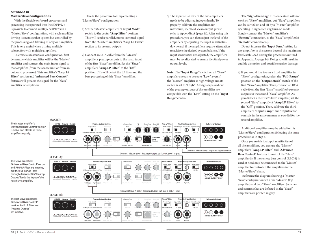
The Master amplifier’s “Advanced Bass Control” section is active and affects all three amplifiers equally.
This Slave amplifier’s “Advanced Bass Control” section and AMP LP Filter are inactive, but the
+12VDC Ground Remote |
|
| Preamp Output Section | Infrasonic Filter |
| “Q” |
|
| Center Freq. | Boost (dB) | Amp LP Filter |
|
| Amplifier Input Section | Subwoofer Output | ||||||||||||||||||||||
| Output Mode | Filter Slope |
| Mode | 1.6 |
|
|
| 40 |
|
| +10 | Mode Slope | Input Voltage | Input Sens. Signal Sensing |
| |||||||||||||||||||||
|
| 1.1 |
| 2.7 | 30 |
| 60 | +4 |
| +13 |
| ||||||||||||||||||||||||||
|
|
|
|
|
|
|
|
|
|
|
| 0.7 |
|
|
| 25 |
|
|
| 75 |
|
|
|
|
|
|
|
|
|
|
|
|
|
|
|
|
|
|
|
|
|
|
|
|
|
|
|
|
|
|
|
|
|
|
|
|
|
|
|
|
|
|
|
|
|
|
|
|
|
|
|
|
|
|
|
| Full Range Amp Filter Out Filter | 12dB 24dB |
| Off On | 0.5 |
| 4.3 | 20 | 80 | 0 | +15 | Off 12dB 24dB |
| Low High |
|
| Off On |
| |||||||||||||||||||
|
| 65 | Filter Mode |
| 30 | Bass EQ |
|
| 65 |
| 55 | 80 | 22 | 45 | Advanced | 55 | 80 | ||
500/1v2 |
|
|
|
|
|
|
|
| |
45 | 100 |
| 18 | 55 |
| Bass | 45 | 100 | |
Monoblock Subwoofer Amplifier | 40 | 200 | LP HP | 15 | 60 | Off On | Control | 40 | MONO OUTPUT ONLY |
| 200 |
Left Output Right Output | Filter Freq. (Hz) | Infrasonic Freq. (Hz) | Remote Bass Port | Filter Freq. (Hz) | Left Ch. | Right Ch. |
Connect Master 500/1 Input to Signal Source
Connect Master 500/1 Preamp Output to Slave A 500/1 Input
Slave (A):
+12VDC Ground Remote | Preamp Output Section | Infrasonic Filter | “Q” | Center Freq. | Boost (dB) | Amp LP Filter | Amplifier Input Section | Subwoofer Output | |||
| Output Mode | Filter Slope | Mode | 1.6 |
| 40 |
| +10 | Mode Slope | Input Voltage Input Sens. Signal Sensing |
|
| 1.1 | 2.7 30 | 60 | +4 | +13 |
| |||||
|
|
| 0.7 |
| 25 | 75 |
|
|
|
|
Full Range Amp Filter Out Filter | 12dB 24dB | Off On | 0.5 | 4.3 | 20 | 80 | 0 | +15 Off 12dB 24dB | Low High | Off On |
|
| 65 | Filter Mode |
| 30 | Bass EQ |
|
| 65 |
| 55 | 80 | 22 | 45 | Advanced | 55 | 80 | ||
500/1v2 |
|
|
|
|
|
|
|
| |
45 | 100 |
| 18 | 55 |
| Bass | 45 | 100 | |
Monoblock Subwoofer Amplifier | 40 | 200 | LP HP | 15 | 60 | Off On | Control | 40 | MONO OUTPUT ONLY |
| 200 |
Left Output Right Output | Filter Freq. (Hz) | Infrasonic Freq. (Hz) | Remote Bass Port | Filter Freq. (Hz) | Left Ch. | Right Ch. |
Additional amplifiers may be added to this
“Master/Slave” configuration following the same
procedure as in step 4.
Once you match the input sensitivities of
all the amplifiers, you can use the “Master” amplifier’s “Amp LP Filter” and “Advanced Bass Control” features to control the “Slave” amplifier(s). If the remote bass control
amplifier to control all the amplifiers in the
“Master/Slave” chain.
Reference the diagram showing a “Master/ Slave” configuration with one “Master” (top amplifier) and two “Slave” amplifiers. Switches and controls that are defeated in the “Slave”
The last Slave amplifier’s “Advanced Bass Control” section, AMP LP Filter and “Preamp Output”
are inactive.
Connect Slave A 500/1 Preamp Output to Slave B 500/1 Input
Slave (B): |
|
|
|
|
|
|
|
|
|
|
|
|
|
|
|
|
|
|
| |
+12VDC | Ground | Remote | Preamp Output Section |
| Infrasonic Filter | “Q” |
| Center Freq. | Boost (dB) | Amp LP Filter | Amplifier Input Section | Subwoofer Output | ||||||||
|
|
| Output Mode | Filter Slope |
|
| Mode | 1.6 |
|
| 40 | +10 |
| Mode Slope | Input Voltage | Input Sens. | Signal Sensing |
| ||
|
|
|
|
| 1.1 | 2.7 | 30 | 60 | +4 | +13 |
| |||||||||
|
|
|
|
|
|
|
|
| 0.7 |
| 25 | 75 |
|
|
|
|
|
|
|
|
|
|
| Full Range Amp Filter Out Filter | 12dB 24dB |
|
| Off On | 0.5 | 4.3 | 20 | 80 | 0 | +15 | Off 12dB 24dB | Low High |
| Off On |
| ||
|
|
|
|
| 65 | Filter Mode |
| 30 | Bass EQ |
|
|
|
|
|
| 65 |
|
|
|
|
|
|
|
| 55 | 80 | 22 | 45 |
|
|
| Advanced | 55 | 80 |
|
|
|
| |||
| 500/1v2 |
|
|
|
|
|
|
|
|
|
|
|
|
|
|
|
| |||
|
| 45 | 100 |
| 18 | 55 |
|
|
|
| Bass |
| 45 | 100 |
|
|
| MONO OUTPUT ONLY | ||
Monoblock Subwoofer Amplifier |
| 40 | 200 | LP HP | 15 | 60 | Off On |
|
|
| Control |
| 40 | 200 |
|
|
| |||
Left Output Right Output | Filter Freq. (Hz) | Infrasonic Freq. (Hz) | Remote Bass Port | Filter Freq. (Hz) | Left Ch. | Right Ch. |
amplifiers are printed in gray.
18 JL Audio - 500/1v2 Owner’s Manual | 19 |