536636-UIM-D-1211

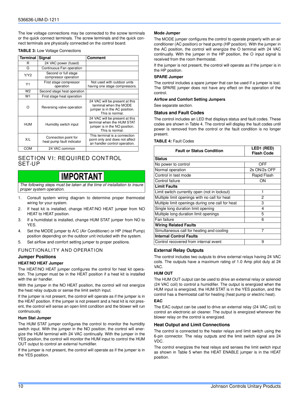
The low voltage connections may be connected to the screw terminals or the quick connect terminals. The screw terminals and the quick con- nect terminals are physically connected on the control board.

TABLE 3: Low Voltage Connections


Terminal

Signal

Comment

R

24 VAC power (fused)


G

Continuous Fan operation


Y/Y2

Second or full stage


compressor operation


Y1

First stage compressor

Not used with outdoor units

operation

having one stage compressors.


W2

Second stage heat operation


W1

First stage heat operation


24 VAC will be present at this

O

Reversing valve operation

terminal when the MODE

jumper is in the AC position.


This is normal.


24 VAC will be present at this

HUM

Humidity switch input

terminal when the HUM STAT

jumper is in the NO position.


This is normal.


Connection point for

This terminal is a connection

X/L

point only and does not affect

heat pump fault indicator


air handler control operation.


COM

24 VAC common


SECTION VI: REQUIRED CONTROL SET-UP

The following steps must be taken at the time of installation to insure proper system operation.

1.Consult system wiring diagram to determine proper thermostat wiring for your system.

2.If heat kit is installed, change HEAT/NO HEAT jumper from NO HEAT to HEAT position.

3.If a humidistat is installed, change HUM STAT jumper from NO to YES.

4.Set the MODE jumper to A/C (Air Conditioner) or HP (Heat Pump) position depending on the outdoor unit included with the system.

5.Set airflow and comfort setting jumper to proper positions.

FUNCTIONALITY AND OPERATION

Jumper Positions

HEAT/NO HEAT Jumper

The HEAT/NO HEAT jumper configures the control for heat kit opera- tion. The jumper must be in the HEAT position if a heat kit is installed with the air handler.

With the jumper in the NO HEAT position, the control will not energize the heat relay outputs or sense the limit switch input.

If the jumper is not present, the control will operate as if the jumper is in the HEAT position. If the jumper is not present and a heat kit is not pres- ent, the control will sense an open limit condition and the blower will run continuously.

Hum Stat Jumper

The HUM STAT jumper configures the control to monitor the humidity switch input. With the jumper in the NO position, the control will ener- gize the HUM terminal with 24 VAC continually. With the jumper in the YES position, the control will monitor the HUM input to control the HUM OUT output to control an external humidifier.

If the jumper is not present, the control will operate as if the jumper is in the YES position.

Mode Jumper

The MODE jumper configures the control to operate properly with an air conditioner (AC position) or heat pump (HP position). With the jumper in the AC position, the control will energize the O terminal with 24 VAC continually. With the jumper in the HP position, the O input signal is received from the room thermostat.

If the jumper is not present, the control will operate as if the jumper is in the HP position.

SPARE Jumper

The control includes a spare jumper that can be used if a jumper is lost. The SPARE jumper does not have any effect on the operation of the control.

Airflow and Comfort Setting Jumpers

See separate section.

Status and Fault Codes

The control includes an LED that displays status and fault codes. These codes are shown in Table 4. The control will display the fault codes until power is removed from the control or the fault condition is no longer present.

TABLE 4: Fault Codes

Fault or Status Condition

LED1 (RED)

Flash Code


Status


No power to control

OFF

Normal operation

2s ON/2s OFF

Control in test mode

Rapid Flash

Control failure

ON

Limit Faults


Limit switch currently open (not in lockout)

1

Multiple limit openings with no call for heat

2

Multiple limit openings during one call for heat

3

Single long duration limit opening

4

Multiple long duration limit openings

5

Fan failure

6

Wiring Related Faults


Simultaneous call for heating and cooling

7

Internal Control Faults


Control recovered from internal event

9

External Relay Outputs

The control includes two outputs to drive external relays having 24 VAC coils. The outputs have a maximum rating of 1.0 Amp pilot duty at 24 VAC.

HUM OUT

The HUM OUT output can be used to drive an external relay or solenoid (24 VAC coil) to control a humidifier. The output is energized when the HUM input is energized, the HUM STAT is in the YES position, and the control has a thermostat call for heating (heat pump or electric heat).

EAC

The EAC output can be used to drive an external relay (24 VAC coil) to control an electronic air cleaner. The output is energized whenever the blower relay on the control is energized.

Heat Output and Limit Connections

The control is connected to the heater relays and limit switch using the 6-pin connector. The relay outputs and the limit switch signal are 24 VDC.

The control energizes the heat relays and senses the limit switch input as shown in Table 5 when the HEAT ENABLE jumper is in the HEAT position.

10

Johnson Controls Unitary Products

Page 10
Image 10
Johnson Controls AV*(C) Series installation manual Section VI Required Control SET-UP, Functionality and Operation

AV*(C) Series specifications

Johnson Controls has long been a leader in the field of building management systems, and the AV*(C) Series is a testament to its commitment to innovation and excellence. Designed with the modern-day facility in mind, the AV*(C) Series combines advanced features, cutting-edge technologies, and robust characteristics to deliver top-tier performance and reliability for building operations.

One of the standout features of the AV*(C) Series is its exceptional flexibility. The series offers a range of controller options that cater to various application needs, ensuring that building managers can tailor their systems to suit specific requirements. This adaptability is complemented by its scalable architecture, which allows for seamless expansion as building needs evolve over time.

Another major highlight of the AV*(C) Series is its intuitive user interface. The system provides an easy-to-navigate platform that simplifies monitoring and control tasks. Users can access real-time data and analytics at their fingertips, enhancing decision-making processes and enabling proactive management of building systems. The graphical display is user-friendly, making it simple for facility staff to respond promptly to any operational issues.

In terms of technology, the AV*(C) Series integrates advanced communication protocols such as BACnet, which ensures interoperability with various building automation systems. This technology ensures that different devices can communicate effectively, streamlining the overall operation of the facility. The controllers also support multiple I/O configurations, which allow for greater customization and setup flexibility.

Energy efficiency is at the forefront of the AV*(C) Series design. The system incorporates intelligent algorithms that optimize energy usage, helping organizations reduce their carbon footprint and operational costs. By continuously monitoring system performance and adjusting settings in real-time, the AV*(C) Series contributes to sustainable building management.

Reliability is also a hallmark of the AV*(C) Series. Built with durable components and designed to withstand diverse environmental conditions, it ensures consistent performance and longevity. The system features redundant power supplies and robust fail-safes to keep operations running smoothly, minimizing downtime.

In conclusion, the Johnson Controls AV*(C) Series is an advanced solution for building management that combines flexibility, user-friendly design, cutting-edge communication technology, energy efficiency, and reliability. These characteristics make it an excellent choice for organizations looking to enhance their facility operations and improve overall performance.