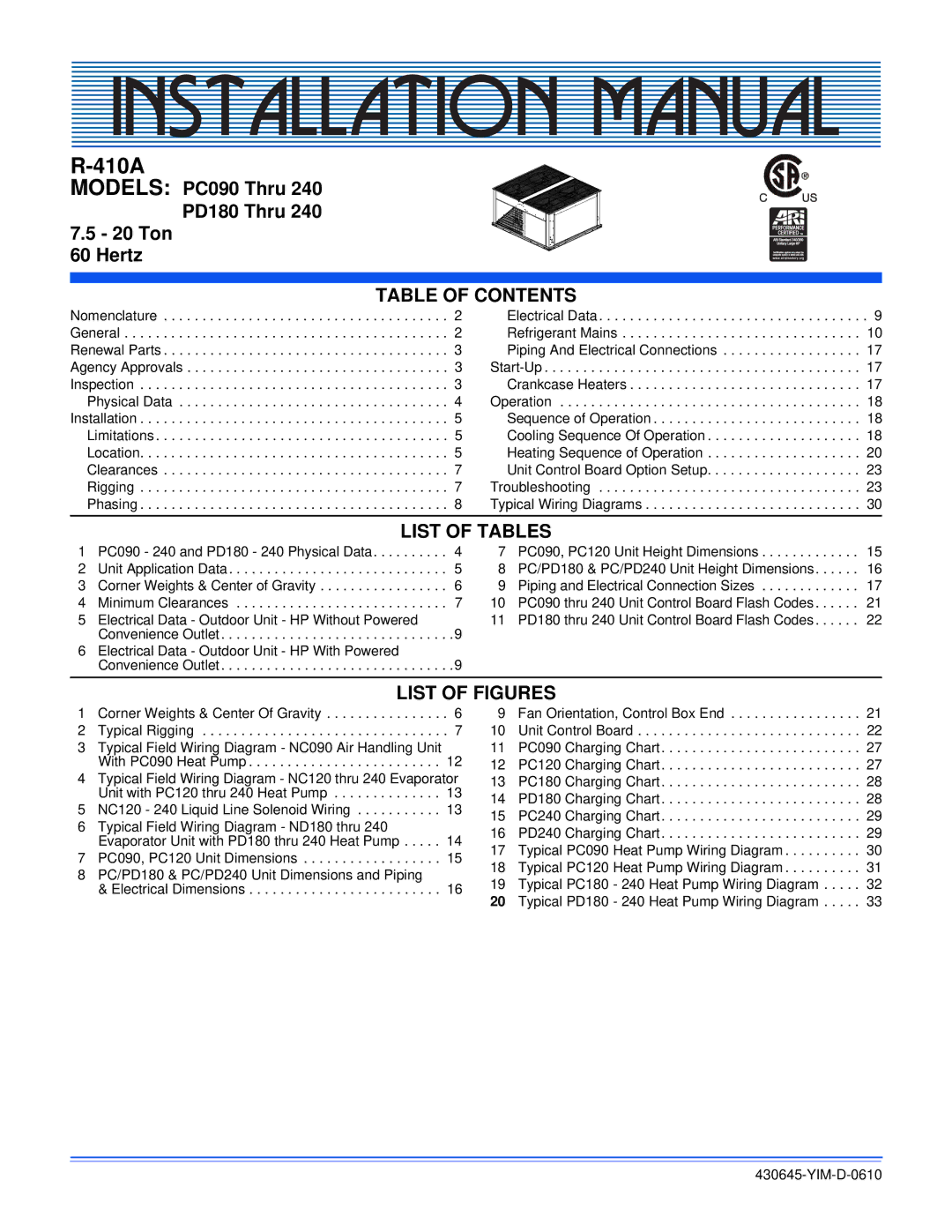
PC090 THRU 240, PD 180 THRU 240 specifications
Johnson Controls has long been a leader in the HVAC and building efficiency industry, and the Johnson Controls PC090 THRU 240 and PD 180 THRU 240 series of commercial rooftop units exemplify their commitment to innovation and energy efficiency. These units are designed to provide optimal performance for a wide range of commercial applications, ensuring comfortable indoor climates while maintaining energy savings.One of the standout features of the Johnson Controls PC and PD series is their advanced cooling and heating capabilities. Both series can operate efficiently across a varied range of capacities, typically from 90,000 to 240,000 BTU/h for the PC series and 180,000 to 240,000 BTU/h for the PD series. This versatility allows users to select the most appropriate unit size for their specific needs, optimizing performance without wasting energy.
The technology behind these rooftop units includes advanced inverter-driven compressors that enable variable-speed operation. This feature allows for precise temperature control, resulting in enhanced comfort and reduced energy usage. The units also integrate smart controls that enable easy monitoring and management, ensuring that the HVAC system can adapt to changes in occupancy or external weather conditions.
Another notable characteristic of the Johnson Controls rooftop units is their robust construction and reliability. Designed for outdoor use, these units can withstand harsh weather conditions while maintaining operational efficiency. They are equipped with corrosion-resistant materials and protective enclosures to prolong the life of the equipment.
The units are also engineered with eco-friendliness in mind, utilizing refrigerants with low global warming potential to minimize their environmental impact. Furthermore, their energy-efficient designs often qualify for various energy incentives, providing businesses an additional return on investment.
Ease of installation and maintenance is another hallmark of the PC and PD series. With a modular design, these units can be easily transported and installed. Maintenance tasks are simplified, allowing facility management teams to perform regular service checks efficiently and effectively.
Overall, the Johnson Controls PC090 THRU 240 and PD 180 THRU 240 series stand out in the commercial HVAC market due to their flexibility, advanced technology, and dedication to energy efficiency and environmental responsibility. These units not only meet modern energy codes but also contribute to a sustainable future with their innovative features and reliable performance.

