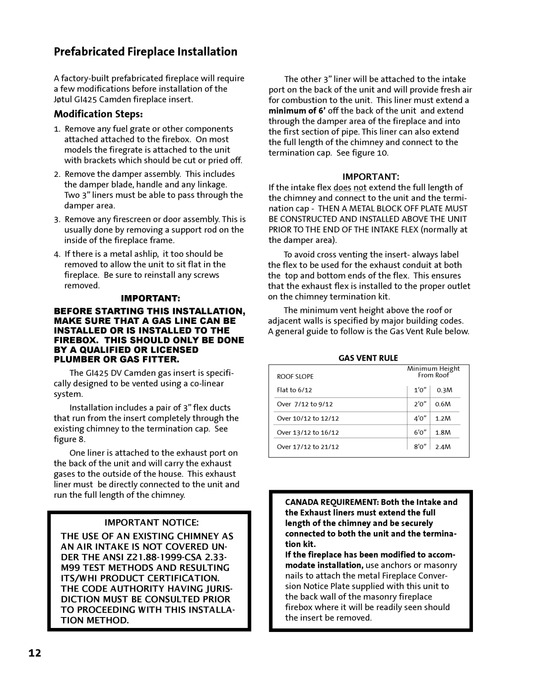
GI 425 DV specifications
The Jotul GI 425 DV is a beautifully designed gas stove that blends traditional aesthetics with modern technology, making it a popular choice for homeowners seeking warmth and style. This versatile unit is part of the Jotul brand’s renowned range of gas appliances, allowing users to enjoy the charm of a fire without the hassle of wood.One of the standout features of the Jotul GI 425 DV is its striking design. It is available in various finishes, including a classic black or a more contemporary white enamel, enabling it to fit seamlessly into a variety of interior decor styles. The large glass door provides a clear view of the flame, enhancing the ambiance of any room while also allowing for easy monitoring of the fire.
In terms of performance, the Jotul GI 425 DV is engineered for efficiency. The stove utilizes a Direct Vent system, which ensures that air from outside is drawn in for combustion, while exhaust gases are expelled outside. This helps to maintain a comfortable indoor environment without compromising air quality. Additionally, the stove offers adjustable flame height and heat output, allowing users to tailor the warmth to their needs.
The appliance is equipped with advanced technology, such as a standing pilot light and an igniter, which ensures quick and reliable starts, even during colder months. The internal heat exchanger distributes warmth evenly throughout the room, enhancing heating efficiency. This model also features a remote control option, enabling users to adjust settings from the comfort of their sofa.
The Jotul GI 425 DV is designed to meet modern environmental standards, incorporating a low-emission gas burner system. This means it produces fewer pollutants while providing the same amount of heat, making it a more eco-friendly choice compared to traditional wood stoves.
Another important characteristic of the Jotul GI 425 DV is its safety features. With a robust build and advanced safety shut-off systems, users can enjoy peace of mind while using the stove, knowing that their home is safe.
In conclusion, the Jotul GI 425 DV gas stove combines elegant design, cutting-edge technology, and efficient performance. With its customizable features and environmental considerations, it is an ideal choice for anyone looking to add both warmth and style to their living space while benefiting from the convenience of gas heating.

