Connections
Connecting to a Cable Box and VCR
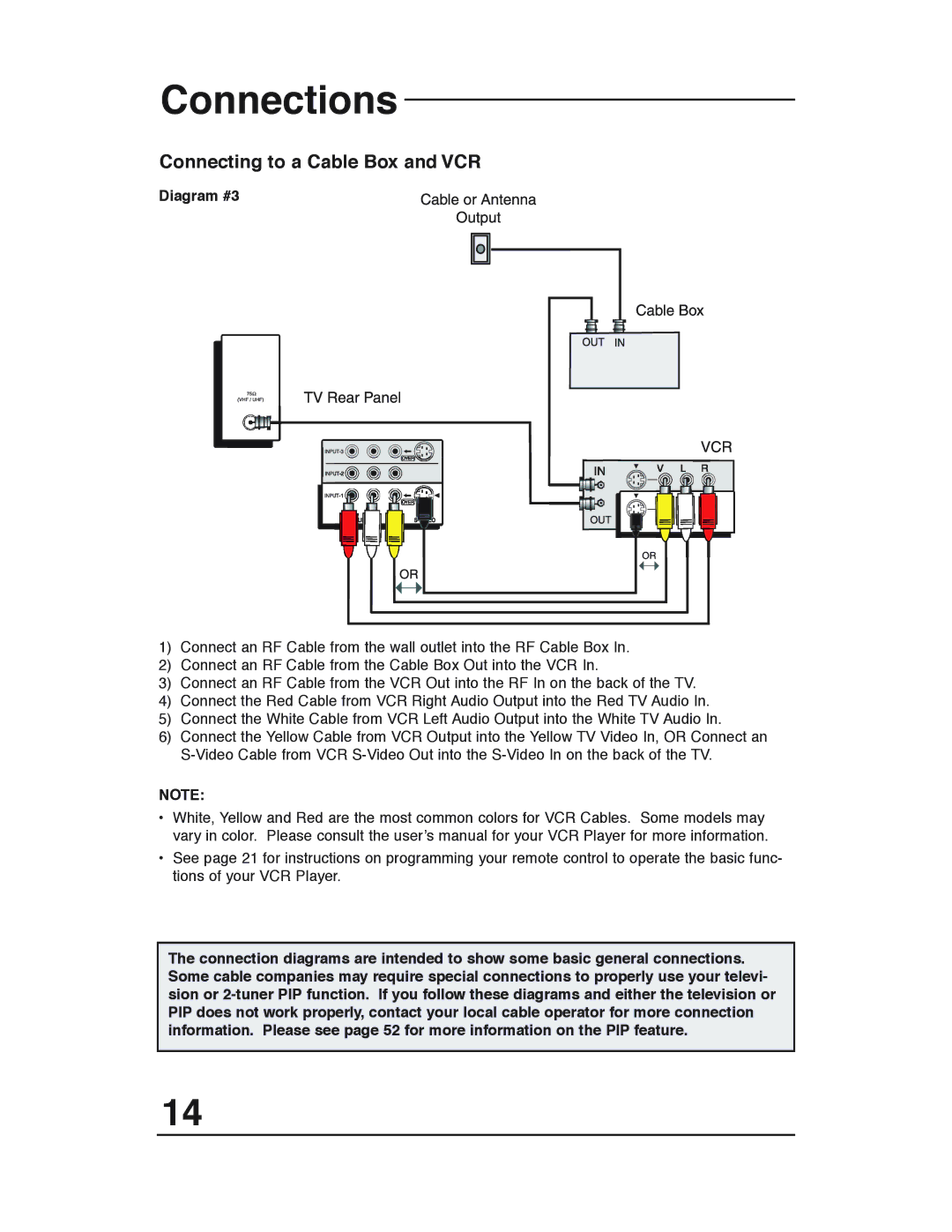
Diagram #3
1)Connect an RF Cable from the wall outlet into the RF Cable Box In.
2)Connect an RF Cable from the Cable Box Out into the VCR In.
3)Connect an RF Cable from the VCR Out into the RF In on the back of the TV.
4)Connect the Red Cable from VCR Right Audio Output into the Red TV Audio In.
5)Connect the White Cable from VCR Left Audio Output into the White TV Audio In.
6)Connect the Yellow Cable from VCR Output into the Yellow TV Video In, OR Connect an
NOTE:
•White, Yellow and Red are the most common colors for VCR Cables. Some models may vary in color. Please consult the user’s manual for your VCR Player for more information.
•See page 21 for instructions on programming your remote control to operate the basic func- tions of your VCR Player.
The connection diagrams are intended to show some basic general connections. Some cable companies may require special connections to properly use your televi- sion or
14