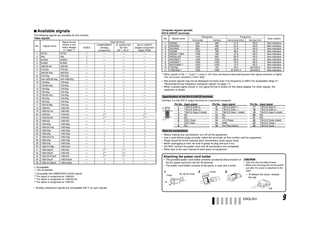
7Available signals
The following signals are available for this monitor.
Video signals
|
| Signal format |
| Input terminal |
| ||
No. | Signal name | shown in the |
| COMPONENT | E. AUDIO HD/ | ||
status display | VIDEO | (Analog | SD SDI | (Digital component/ | |||
|
| ||||||
|
| (☞ page 7) |
| component) | (IN 1, IN 2)*1 | digital RGB) | |
1 | NTSC | NTSC | √ | — | — | — | |
2 | PAL | PAL | √ | — | — | — | |
3 | B/W50 | B/W50 | √ | — | — | — | |
4 | B/W60 | B/W60 | √ | — | — | — | |
5 | 480/59.94i | 480/60i | — | √ | √ | — | |
6 | 576/50i | 576/50i | — | √ | √ | — | |
7 | 480/59.94p | 480/60p | — | √ | — | √ | |
8 | 576/50p | 576/50p | — | √ | — | √ | |
9 | 640∗480/59.94p | 640∗480/60p | — | — | — | √ | |
10 | 720/60p | 720/60p | — | √ | √ | √ | |
11 | 720/59.94p | 720/60p | — | √ | √ | √ | |
12 | 720/50p | 720/50p | — | √ | √ | √ | |
13 | 720/30p | 720/30p | — | √ | √ | — | |
14 | 720/29.97p | 720/30p | — | √ | √ | — | |
15 | 720/25p | 720/25p | — | √ | √ | — | |
16 | 720/24p | 720/24p | — | √ | √ | — | |
17 | 720/23.98p | 720/24p | — | √ | √ | — | |
18 | 1080/60i | 1080/60i | — | √ | √ | √ | |
19 | 1080/59.94i | 1080/60i | — | √ | √ | √ | |
20 | 1035/60i | 1035/60i | — | √*2 | √ | √*2 | |
21 | 1035/59.94i | 1035/60i | — | √*3 | √ | √*3 | |
22 | 1080/50i | 1080/50i | — | √ | √ | √ | |
23 | 1080/60p | 1080/60p | — | — | — | √ | |
24 | 1080/59.94p | 1080/60p | — | — | — | √ | |
25 | 1080/50p | 1080/50p | — | — | — | √ | |
26 | 1080/30p | 1080/30p | — | √ | √ | √ | |
27 | 1080/29.97p | 1080/30p | — | √ | √ | √ | |
28 | 1080/25p | 1080/25p | — | √ | √ | √ | |
29 | 1080/24p | 1080/24p | — | √ | √ | √ | |
30 | 1080/23.98p | 1080/24p | — | √ | √ | √ | |
31 | 1080/30psF | 1080/60i | — | √*2 | √*2 | — | |
32 | 1080/25psF | 1080/50i | — | √*4 | √*4 | — | |
Computer signals (preset)
DVI-D (HDCP) terminals
No. | Signal name | Resolution |
| Frequency | Scan system | ||
Horizontal |
| Vertical | Horizontal (kHz) | Vertical (Hz) | |||
|
|
|
| ||||
1 | VGA60 | 640 |
| 480 | 31.5 | 59.9 | |
2 | WVGA60 | 852 |
| 480 | 31.5 | 59.9 | |
3 | SVGA60 | 800 |
| 600 | 37.9 | 60.3 | |
4 | XGA60 | 1024 |
| 768 | 48.4 | 60.0 | |
5 | WXGA (1280) | 1280 |
| 768 | 47.8 | 60.0 | |
6 | WXGA+60 | 1440 |
| 900 | 55.9 | 60.0 | |
7 | SXGA60*5 | 1280 |
| 1024 | 64.0 | 60.0 | |
8 | UXGA60*5 | 1600 |
| 1200 | 75.0 | 60.0 | |
9 | WUXGA60*5 | 1920 |
| 1200 | 74.0 | 60.0 | |
10 | 720/60p | 1280 |
| 720 | 45.0 | 59.9/60.0 | |
11 | 1080/60p*5 | 1920 |
| 1080 | 67.5/67.4 | 59.9/60.0 | |
*5 When signals of No. 7 – 9 and 11 come in, thin lines will become obscured because their signal resolution is higher than the screen resolution (1440 x 900).
•
•When a preset signal comes in, the signal format is shown on the status display. For other signals, the resolution is shown.
Specification of the DVI-D (HDCP) terminal
Connect it to the
Pin No. | Input signal |
| Pin No. | Input signal |
| Pin No. | Input signal |
1 | T.M.D.S Data 2– |
| 9 | T.M.D.S Data 1– |
| 17 | T.M.D.S Data 0– |
2 | T.M.D.S Data 2+ |
| 10 | T.M.D.S Data 1+ |
| 18 | T.M.D.S Data 0+ |
3 | T.M.D.S Data 2 shield |
| 11 | T.M.D.S Data 1 shield |
| 19 | T.M.D.S Data 0 shield |
4 | NC |
| 12 | NC |
| 20 | NC |
5 | NC |
| 13 | NC |
| 21 | NC |
6 | DDC Clock |
| 14 | +5 V Power |
| 22 | T.M.D.S Clock shield |
7 | DDC Data |
| 15 | GND |
| 23 | T.M.D.S Clock+ |
8 | NC |
| 16 | Hot Plug Detect |
| 24 | T.M.D.S Clock– |
Note for connections
•Before making any connections, turn off all the equipment.
•Use a cord whose plugs correctly match the terminals on this monitor and the equipment.
•Plugs should be firmly inserted; poor connections could cause noise.
•When unplugging a cord, be sure to grasp its plug and pull it out.
•DO NOT connect the power cord until all connections are completed.
•Refer also to the user manual of each piece of equipment.
33 | 1080/29.97psF | 1080/60i | — | √*3 | √*3 | — |
34 | 1080/24psF | 1080/24psf | — | √ | √ | — |
35 | 1080/23.98psF | 1080/24psf | — | √ | √ | — |
√: Acceptable
—: Not acceptable
*1 Compatible with EMBEDDED AUDIO signals *2 The signal is recognized as 1080/60i.
*3 The signal is recognized as 1080/59.94i. *4 The signal is recognized as 1080/50i.
Attaching the power cord holder
•The provided power cord holder prevents accidental disconnection of the AC power cord from the AC IN terminal.
•The power cord holder consists of two parts, a case and a cover.
12 Cover 3
Case | AC IN terminal |
|
CAUTION
•Use only the provided screws.
•Make sure the plug will not be pulled out after the cover is attached to the case.
•To detach the cover, release the tab.
• Analog component signals are compatible with Y on sync signals.
Tab
ENGLISH9