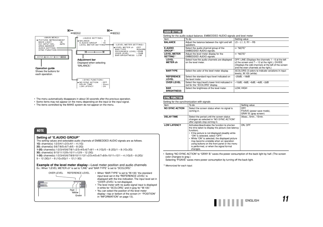
Adjustment bar Displayed when selecting “BALANCE.”
Operation guide Shows the buttons for each operation.
•The menu automatically disappears in about 30 seconds after the previous operation.
•Some items may not appear on the menu depending on the input or the input signal.
•The items controlled by the MAKE system do not appear on the menu.
NOTE
Setting of “E.AUDIO GROUP”
The setting values and selectable audio channels of EMBEDDED AUDIO signals are as follows. 1G: channel(s) 1/2/3/4/1+2/3+4/1 – 4 (1G)
2G: channel(s) 5/6/7/8/5+6/7+8/5 – 8 (2G)
3G: channel(s) 9/10/11/12/9+10/11+12/9 – 12 (3G)
Example of the level meter
Ex.: When “LEVEL METER ch” is set to “LINE” and “BAR TYPE” is set to “3COLORS.”
AUDIO SETTING
Setting for the audio output balance, EMBEDDED AUDIO signals and level meter
Item | To do | Setting value | |
BALANCE | Adjust the balance between the right and left | L5 – L1, 0, R1 – R5 | |
|
| speakers. |
|
E.AUDIO | Select the audio channel group of the | ☞ “NOTE” | |
GROUP*1 | EMBEDDED AUDIO signals. |
| |
LEVEL METER | Adjust the level meter display for the | ☞ “NOTE” | |
SETTING*1 | EMBEDDED AUDIO signals. |
| |
| LEVEL | Select how the audio channels are displayed | OFF, LINE (Displays the channels 1 – 6 at the left |
| METER ch | on the level meter. | of the screen and 7 – 12 at the right.), DIVIDE |
|
|
| (Displays the odd channels at the left of the screen |
|
|
| and the even channels at the right.) |
| BAR TYPE | Select the color of the level meter display. | 3COLORS (3 colors to indicate variations in input |
|
|
| levels), W.100 (white) |
| REFERENCE | Select the standard input level indicated on | |
| LEVEL | the level meter. |
|
| OVER LEVEL | Select the input level’s lower limit indicated in | |
|
| red for the “3COLORS” display. |
|
| BAR | Select the brightness of the level meter. | LOW, HIGH |
| BRIGHTNESS |
|
|
SYNC FUNCTION
Setting for the synchronization with signals
Item | To do | Setting value |
NO SYNC ACTION | Select the screen status when no signal is | OFF, |
| coming in. | P.SAVE (power save mode), |
|
| GRAY B. (gray screen) |
DELAY TIME | Select the period until the screen status | 30sec., 5min., 15min. |
| changes as selected in “NO SYNC ACTION” |
|
| after signals stop coming in. |
|
LOW LATENCY | Activates/deactivates the function to shorten | ON, OFF |
| the time taken to display the picture (low latency |
|
| function). |
|
| • If the picture is not displayed steadily while |
|
| “ON” is selected, select “OFF.” |
|
| • While “ON” is selected, the displayed picture |
|
| may become unstable when an operation |
|
| using buttons on the front panel or the menu |
|
| is performed, or when the signal format |
|
| changes. |
|
•Setting “NO SYNC ACTION” to “GRAY B.” saves the power consumption of the back light by half. (The screen color changes to gray.)
Selecting “P.SAVE” saves more power consumption by turning off the back light.
*1 Memorized for each input.
OVER LEVEL REFERENCE LEVEL
Red
Yellow
Green
•When “BAR TYPE” is set to “W.100,” the standard input level set in the “REFERENCE LEVEL” is displayed with the line indication. The input level set in “OVER LEVEL” is not displayed.
•The level meter with no audio signal input is displayed in white for “3COLORS,” and in gray for “W.100.”
•You can select the position of the level meter
ENGLISH11