Operation
1Set “PARALLEL TYPE” of “REMOTE SETTING” to “MAKE” or “TRIGGER” in the
2
3When selecting “MAKE” system: Operate each function by
When selecting “TRIGGER” system: Operate each function by pulse control, that is
•When changing the input with MAKE system, only one pin terminal must be
•When selecting the “TRIGGER” system, you can operate only one function at a time. Operate the functions one by one.
7Using the serial communication
You can control the monitor from a personal computer etc. via the
• Consult your dealer for the details of the external control specification.
<Communication specifications>
Input terminal | Cable | Terminal | Communication specifications | |
specification | ||||
|
|
| ||
A straight LAN cable |
| Baud Rate: 4800 bps | ||
A straight cable with a |
| |||
| Data Bits: 8 bits | |||
| connector (male for the monitor, | ☞ See the right | Parity: No parity | |
| female for the personal computer | Stop Bits: 1 bit | ||
|
| |||
| etc.) |
| Flow Control: No control | |
|
|
| Communication Code: ASCII Code | |
|
|
|
|
<Command outline>
All commands consist of the following segments.
Header | Monitor ID | Command ID | Function | Data | Cr (0DH) |
|
|
|
|
|
|
Header
“!”: Operation commands from the personal computer, etc. For details, see <Basic command list> on the right.
“?”: Reference commands from the personal computer, etc.
“@”: Status returns from the monitor
•To start communication, send the connection command from the personal computer etc.
•To terminate the communication, send the termination command from the personal computer etc.
<Basic command list>
No. |
|
|
|
|
| Commands |
|
|
| Functions | Data | ||||
1 | ! | * **1 B | C | N | 1 | Cr |
|
|
|
| Starts communication (connection) | No data | |||
2 | ! | * **1 B | C | N | 0 | Cr |
|
|
|
| Terminates communication (termination) | No data | |||
3 | ! | * **1 B | I | D | S | E | T | x | x*2 | Cr | Assigns the control ID |
| 01 – 99 | ||
4 | ! | * | **1 | B | I | D | R | E | T | Cr |
|
| Initializes the control ID |
| No data |
5 | ! | * | **1 | B | I | D | D | S | P | x | x*2 | Cr | Displays/hides the ID |
| 00: Hide |
| 01: Display | ||||||||||||||
|
|
|
|
|
|
|
|
|
|
|
|
|
|
| |
6 | ! | * | **1 | B | I | D | C | H | K | x | x*2 | Cr | Flashes/hides the selected ID No. of the monitor | 00: Hide | |
|
|
|
|
|
|
|
|
|
|
|
|
|
|
| 01: Display |
7 | ! | * | **1 | B | M | E | N | U | Cr |
|
|
| Displays the MAIN MENU/Quits the menu | No data | |
|
|
| operation |
| |||||||||||
|
|
|
|
|
|
|
|
|
|
|
|
|
|
| |
8 | ! | * **1 B | U | P | Cr |
|
|
|
|
| Moves the cursor upward ( | ) | No data | ||
9 | ! | * **1 B | D | O | W | N | Cr |
|
|
| Moves the cursor downward ( ) | No data | |||
10 | ! | * **1 B | A | D | J | R | Cr |
|
|
| Makes setting/adjustment ( | ) | No data | ||
11 | ! | * **1 B | A | D | J | L | Cr |
|
|
| Makes setting/adjustment ( | ) | No data | ||
12 | ! | * **1 B | S | E | T | U | P | Cr |
|
| Displays the |
| No data | ||
13 | ! | * **1 B | P | W | 1 | Cr |
|
|
|
| Turns on the monitor |
| No data | ||
14 | ! | * **1 B | P | W | 0 | Cr |
|
|
|
| Turns off the monitor (on standby) | No data | |||
15 | ! | * **1 B | I | N | A | Cr |
|
|
|
| Selects “SDI 1” input |
| No data | ||
16 | ! | * **1 B | I | N | B | Cr |
|
|
|
| Selects “SDI 2” input |
| No data | ||
17 | ! | * **1 B | I | N | C | Cr |
|
|
|
| Selects “DVI” input |
| No data | ||
18 | ! | * **1 B | I | N | D | Cr |
|
|
|
| Selects “COMPO.” input |
| No data | ||
19 | ! | * **1 B | I | N | E | Cr |
|
|
|
| Selects “VIDEO” input |
| No data | ||
20 | ! | * **1 B | D | I | S | P | Cr |
|
|
| Displays the status*3 |
| No data | ||
21 | ! | * **1 B | A | M | U | T | E | x | x*2 | Cr | Turns muting on/off |
| 00: Off, 01: On | ||
22 | ! | * | **1 | B | A | S | P | x | x*2 | Cr |
|
| Changes the aspect ratio |
| 00: 4:3, 01: 16:9 |
•“Cr” is 0Dh.
•The commands for starting communication (connection) (No. 1), terminating communication (termination) (No. 2), and turning on the monitor (No. 13) can be used while the monitor is off (on standby).
*1 Enter the monitor’s ID for “ **.” The initial setting of the monitor’s ID is “00.” When connecting several monitors, “00” is a command for controlling all monitors at once.
*2 Enter the appropriate data to “xx”.
*3 Displays the information shown when INPUT SELECT button of the current input is pressed (☞ “About the Status Display” on page 7).
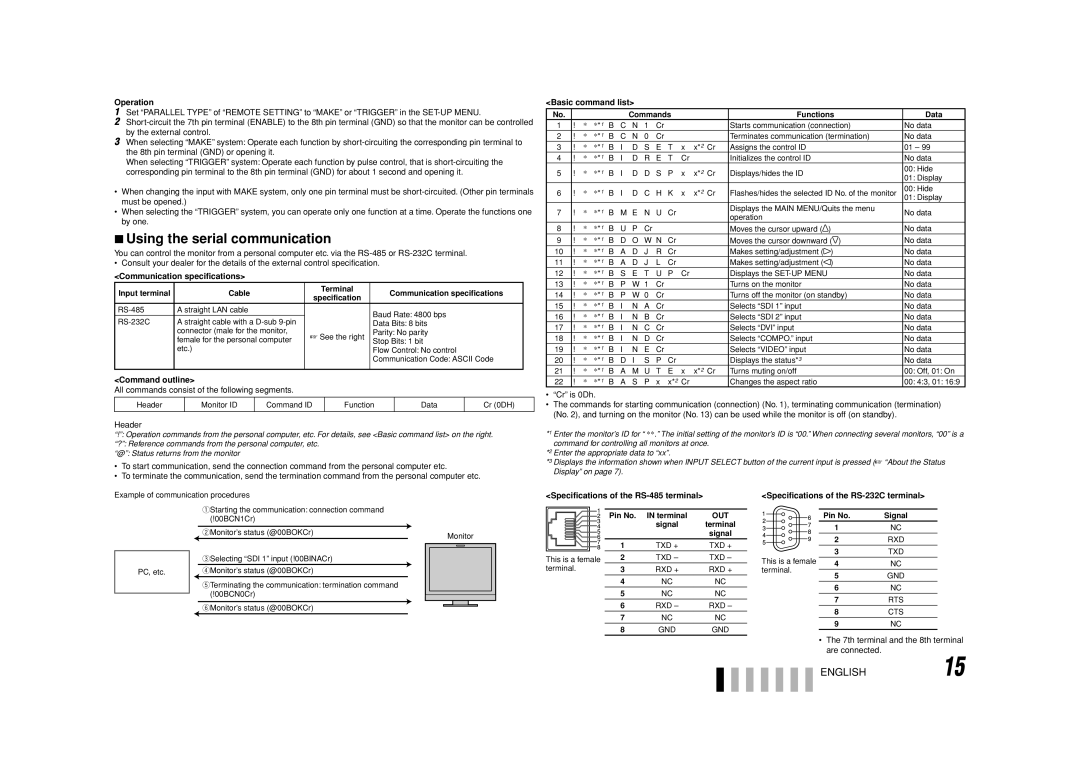
Example of communication procedures
1Starting the communication: connection command (!00BCN1Cr)
|
| 2Monitor’s status (@00BOKCr) |
| Monitor | ||||
|
| 3Selecting “SDI 1” input (!00BINACr) |
|
|
|
|
|
|
|
|
|
|
|
|
|
| |
PC, etc. |
| 4Monitor’s status (@00BOKCr) |
|
|
|
|
|
|
|
| 5Terminating the communication: termination command |
|
|
|
|
|
|
|
| (!00BCN0Cr) |
|
|
|
|
|
|
|
|
|
|
|
|
| ||
|
| 6Monitor’s status (@00BOKCr) |
|
|
|
|
|
|
|
|
|
|
|
|
|
| |
<Specifications of the
|
|
|
|
|
|
|
|
|
|
|
|
|
|
|
|
| Pin No. | IN terminal | OUT |
|
|
|
|
|
|
| |||
|
|
|
|
|
|
|
| signal | terminal |
|
|
|
|
|
|
|
|
| signal |
|
|
|
|
|
|
| 1 | TXD + | TXD + |
|
|
|
|
|
|
| |||
This is a female | 2 | TXD – | TXD – | ||||||
terminal. | 3 | RXD + | RXD + | ||||||
|
|
|
|
|
|
| 4 | NC | NC |
|
|
|
|
|
|
| 5 | NC | NC |
|
|
|
|
|
|
| 6 | RXD – | RXD – |
|
|
|
|
|
|
| 7 | NC | NC |
|
|
|
|
|
|
| 8 | GND | GND |
<Specifications of the RS-232C terminal>
| Pin No. | Signal |
| 1 | NC |
| 2 | RXD |
| 3 | TXD |
This is a female | 4 | NC |
terminal. | 5 | GND |
| ||
| 6 | NC |
| 7 | RTS |
| 8 | CTS |
| 9 | NC |
•The 7th terminal and the 8th terminal are connected.
ENGLISH15