Plasma Display Monitor
Instructions
Risk of Electric Shock Do not Open
Important Safety Instructions
Table of Contents
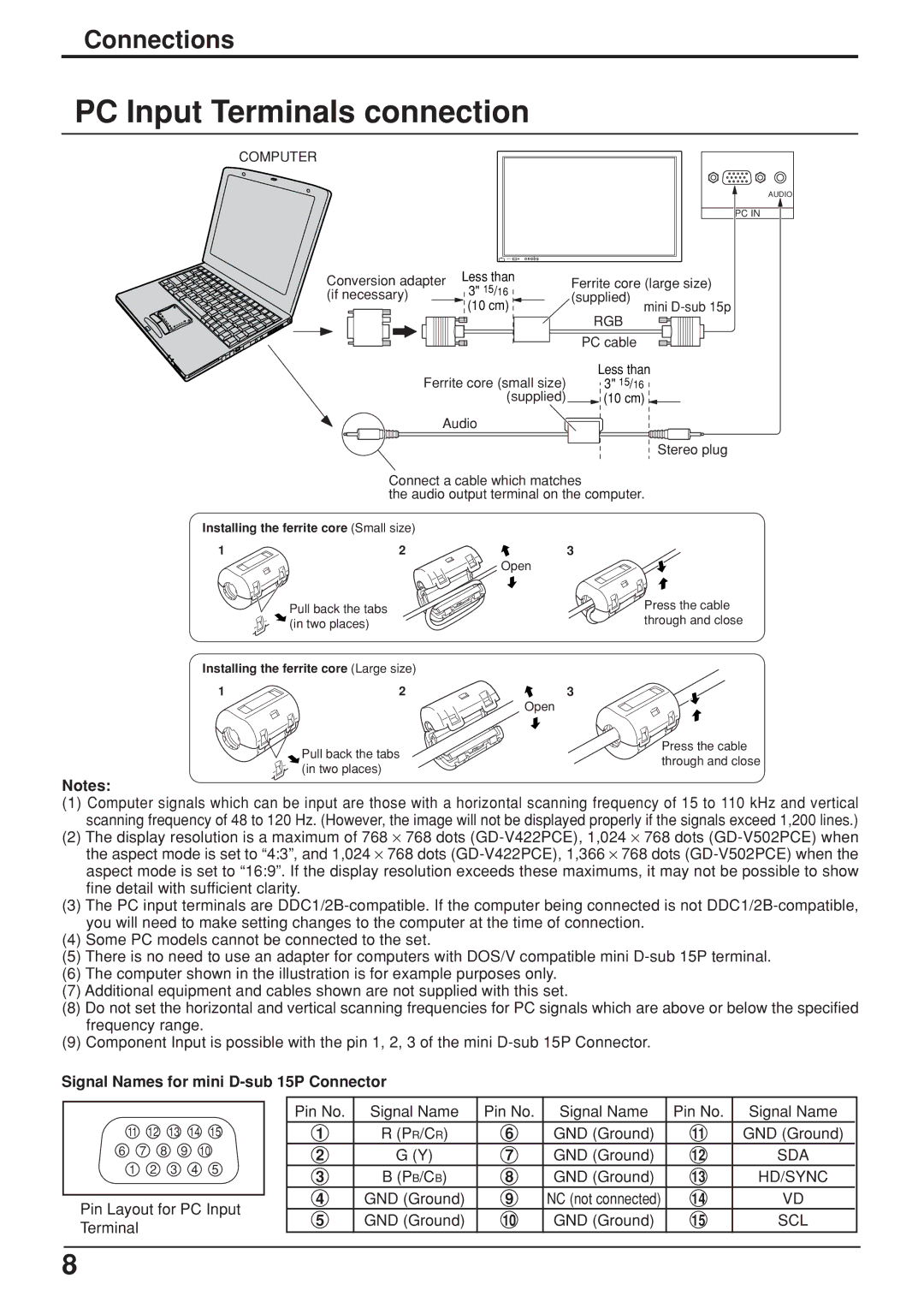
Attach the ferrite core
Trademark Credits
Safety Precautions
Set up
AC Power Supply Cord
If problems occur during use
Cleaning and maintenance
When using the Plasma Display
All of the following accessories are manufactured by JVC
Electric shocks can result if this is not done
Accessories
Accessories Supplied
Remote Control Batteries
Connections
Speakers
AC cord fixing
Signal Names for mini D-sub 15P Connector
PC Input Terminals connection
Installing the ferrite core Large size
Command
Serial Terminals connection
Communication parameters
RGB signal R, G, B, HD, VD
Power on / OFF
Power on / OFF
Connecting the AC plug to the Wall Outlet
AC cord connection
Basic Controls
Normal
Viewing
Press to access
OFF Timer button
Stand-by on / OFF button
Surround button
Settings
On-Screen Menu Displays
Advanced
Time / Power OFF Time
Duration / Saver
Input Signal Selection
Select the Input Signal
Selecting the On-Screen Menu Language
Mode Picture Explanation
Aspect Controls
Normal Zoom Full
Auto Just
Adjusting Picture POSITION/SIZE
Adjusting screen
Size / Clock Phase
Helpful Hint N / Normalize Normalization
Sound Adjustment
Mute
Picture Adjustments
Auto Standard Cinema Dynamic
Normal Cool Warm
Advanced Settings
Present Time Setup
Setup
SET UP Timer
Present Time
SET UP Timer
Power on TIME/POWER OFF Time
Power OFF Time
Power OFF Function
Mode selection
Start setting
Screensaver For preventing after-images
Negative / Scroll selection
Setup of Screensaver Time
Reduces screen after-image
Peak Limit
Side BAR Adjust
OFF, DARK, MID, Bright OFF Dark MID Bright
Press to exit from Screensaver
Digital Zoom
Display the Operation Guide
Select the area of the image to be enlarged
Select the magnification required for the enlarged display
Reduces power consumption
Customizing the Input labels
Setup for Multi Display
How to setup Multi Display
Multi Display Setup
Press to display Multi Display Setup menu Press to select
Press to select 2×2, 3×3
NTSC, PAL, Secam
SET UP for Input Signals
Component / RGB in Select
Component RGB
3D Y / C Filter For Ntsc Video images
Color System / Aspect Auto
Pulldown
If the image becomes unstable
Setting RGB sync signal
Sync
FREQ. kHz / V-FREQ. Hz
Displays the H Horizontal / V Vertical frequencies
Troubleshooting
Plasma Display panel Symptoms Check
Electrical Appliances
Cars / Motorcycles
Video / Component / RGB / PC input signals
Applicable input signals for PC Input mini D-sub 15P ∗ Mark
PAL60
Specifications
GD-V422U GD-V502U
Page
GD-V422U / GD-V502U Plasma Display Monitor
GD-V502PCE
Plasma Display Monitor GD-V422PCEINSTRUCTIONS
Present Time Setup
Important Safety Notice
For Your SAFETY, Please Read the Following Text Carefully
This Apparatus Must be Earthed
Green-and-Yellow Earth
Setup
Do not stick any foreign objects into the Plasma Display
Do not remove the cover or modify it in any way
Clean the power cable regularly to prevent it becoming dusty
Accessories Supply
Observe the following precaution
Requires two R6 batteries
AC cord connection
Optional Video Input Card insert Slots covered
GND Ground Signal Name
SDA HD/SYNC SCL
Norm Zoom
Full Just
Main Power Button On / Off Switch
Remote control Menu Screen on / OFF Power Indicator Sensor
Enter / Aspect
Button see Picture button
SET UP button
Off
Position buttons Digital Zoom see Sound button see
Picture POS./ Size button
Power On / Off and input signal selection
Power On / Off and input signal selection
To Picture adjust menu see
To Sound adjust menu see
Press to access each adjust screen From the unit
Press to Setup
Power on Time
Power OFF Time
Zoom
Just
Auto
Adjusting Picture Pos./ Size
Helpful Hint N / Normalise Normalisation
Pos
Size
Normal
Dynamic
Cinema
Advanced settings
Mute
Bass
Treble
Balance
Button Can be operated Mute button VOL button
Exit
Present Time Setup / Set up Timer
Present Time Setup
Set up Timer
Reversal / Scroll selection
White bar scroll Image Reversal
Off
Screensaver under On, press the R button
Peak limit
Start Time Finish Time
Side Panel Adjustment
Power management
Press to exit from Setup
PC MiniD-sub input PC/COMPONENT/RGB/DVD/STB
Press to select the Multi Display Setup
Press to select 2×2, 3×3
Setup for Input Signals
Component / RGB-in Select
3D Y / C Filter For Ntsc AV images
Component
Colour system / Aspect Auto
Cinema reality
If the picture image becomes unstable
PAL Secam Ntsc
Sync
No Picture No Sound By button on the remote control
Input signal can be displayed
Signal name Horizontal Vertical Component
When Multi Screen
GD-V422PCE GD-V502PCE
GD-V422PCE / GD-V502PCE Plasma Display Monitor