GETTING STARTED EN 7
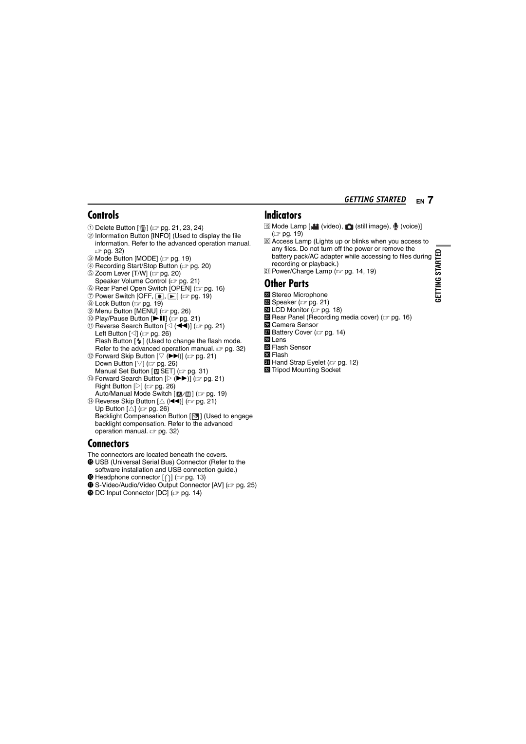
Controls
A Delete Button [![]() ] (☞ pg. 21, 23, 24)
] (☞ pg. 21, 23, 24)
B Information Button [INFO] (Used to display the file information. Refer to the advanced operation manual.
☞pg. 32)
C Mode Button [MODE] (☞ pg. 19)
D Recording Start/Stop Button (☞ pg. 20) E Zoom Lever [T/W] (☞ pg. 20)
Speaker Volume Control (☞ pg. 21)
F Rear Panel Open Switch [OPEN] (☞ pg. 16) G Power Switch [OFF, ![]() ,
, ![]() ] (☞ pg. 19)
] (☞ pg. 19)
H Lock Button (☞ pg. 19)
I Menu Button [MENU] (☞ pg. 26)
J Play/Pause Button [49] (☞ pg. 21)
K Reverse Search Button [w (3)] (☞ pg. 21) Left Button [w] (☞ pg. 26)
Flash Button [ ![]() ] (Used to change the flash mode. Refer to the advanced operation manual. ☞ pg. 32)
] (Used to change the flash mode. Refer to the advanced operation manual. ☞ pg. 32)
L Forward Skip Button [t (6)] (☞ pg. 21) Down Button [t] (☞ pg. 26)
Manual Set Button [ ![]() SET] (☞ pg. 31)
SET] (☞ pg. 31)
M Forward Search Button [e (5)] (☞ pg. 21) Right Button [e] (☞ pg. 26)
Auto/Manual Mode Switch [ ![]()
![]()
![]() ] (☞ pg. 19) N Reverse Skip Button [r (2)] (☞ pg. 21)
] (☞ pg. 19) N Reverse Skip Button [r (2)] (☞ pg. 21)
Up Button [r] (☞ pg. 26)
Backlight Compensation Button [ ![]() ] (Used to engage backlight compensation. Refer to the advanced operation manual. ☞ pg. 32)
] (Used to engage backlight compensation. Refer to the advanced operation manual. ☞ pg. 32)
Indicators
S Mode Lamp [![]()
![]() (video),
(video), ![]() (still image),
(still image), ![]() (voice)] (☞ pg. 19)
(voice)] (☞ pg. 19)
T Access Lamp (Lights up or blinks when you access to any files. Do not turn off the power or remove the battery pack/AC adapter while accessing to files during recording or playback.)
U Power/Charge Lamp (☞ pg. 14, 19)
Other Parts
V Stereo Microphone W Speaker (☞ pg. 21)
X LCD Monitor (☞ pg. 18)
Y Rear Panel (Recording media cover) (☞ pg. 16) Z Camera Sensor
a Battery Cover (☞ pg. 14)
bLens
cFlash Sensor
dFlash
eHand Strap Eyelet (☞ pg. 12)
fTripod Mounting Socket
GETTING STARTED
Connectors
The connectors are located beneath the covers.
O USB (Universal Serial Bus) Connector (Refer to the software installation and USB connection guide.)
P Headphone connector [ ![]() ] (☞ pg. 13)
] (☞ pg. 13)
Q
RDC Input Connector [DC] (☞ pg. 14)
