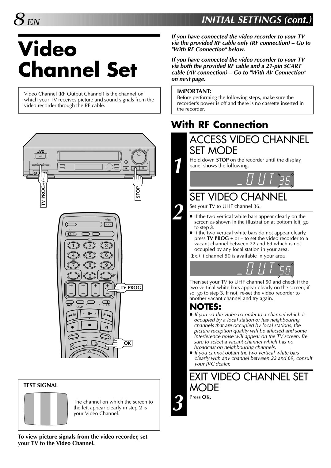
HR-DD848E specifications
The JVC HR-DD848E is a notable video cassette recorder (VCR) that emerged as a significant device in the late 1990s. It is particularly known for its advanced features and technological advancements that set it apart from conventional VCRs of its time. As part of JVC's esteemed line of video equipment, the HR-DD848E stands out for its ability to deliver high-quality playback and recording, marking it a favorite among enthusiasts and casual users alike.One of the main features of the HR-DD848E is its Dual Play capability, allowing users to play back different formats without the need for additional equipment. The device supports both standard VHS tapes as well as the more advanced S-VHS format. S-VHS, known for its superior resolution and video quality compared to standard VHS, is complemented by the VCR’s built-in digital noise reduction and picture enhancement technology. This ensures that the playback experience is crisp and clear, regardless of tape quality.
Another distinguishing characteristic of the JVC HR-DD848E is its user-friendly interface. The device features straightforward controls and an intuitive on-screen menu, making it easy for individuals of all ages to operate. The included remote control also contributes to the user's convenience, providing access to various functionalities such as fast-forward, rewind, and pause.
The HR-DD848E is equipped with several advanced recording features. The Time Base Corrector (TBC) and the LP (Long Play) mode enhance the recording quality, allowing for longer playtime with satisfactory image clarity. The device also supports programming capabilities, enabling users to set timers for recordings, ensuring that they never miss their favorite shows, even during busy times.
Moreover, it features an AV input/output, enabling connectivity with other devices, such as cameras or additional video sources, making it versatile for various multimedia applications.
In summary, the JVC HR-DD848E is a remarkable VCR that encapsulates the technological innovations of its era. With features that enhance playback and recording quality, user-friendly operation, and the ability to connect with other devices, it represents a significant leap forward in home video technology. Whether for casual viewing or archiving cherished memories, the HR-DD848E remains a memorable part of video recording history.

