To prevent short circuits, we recommend that you disconnect the battery’s negative terminal and make all electrical connections before installing the receiver.
•Be sure to ground this unit to the car’s chassis again after installation.
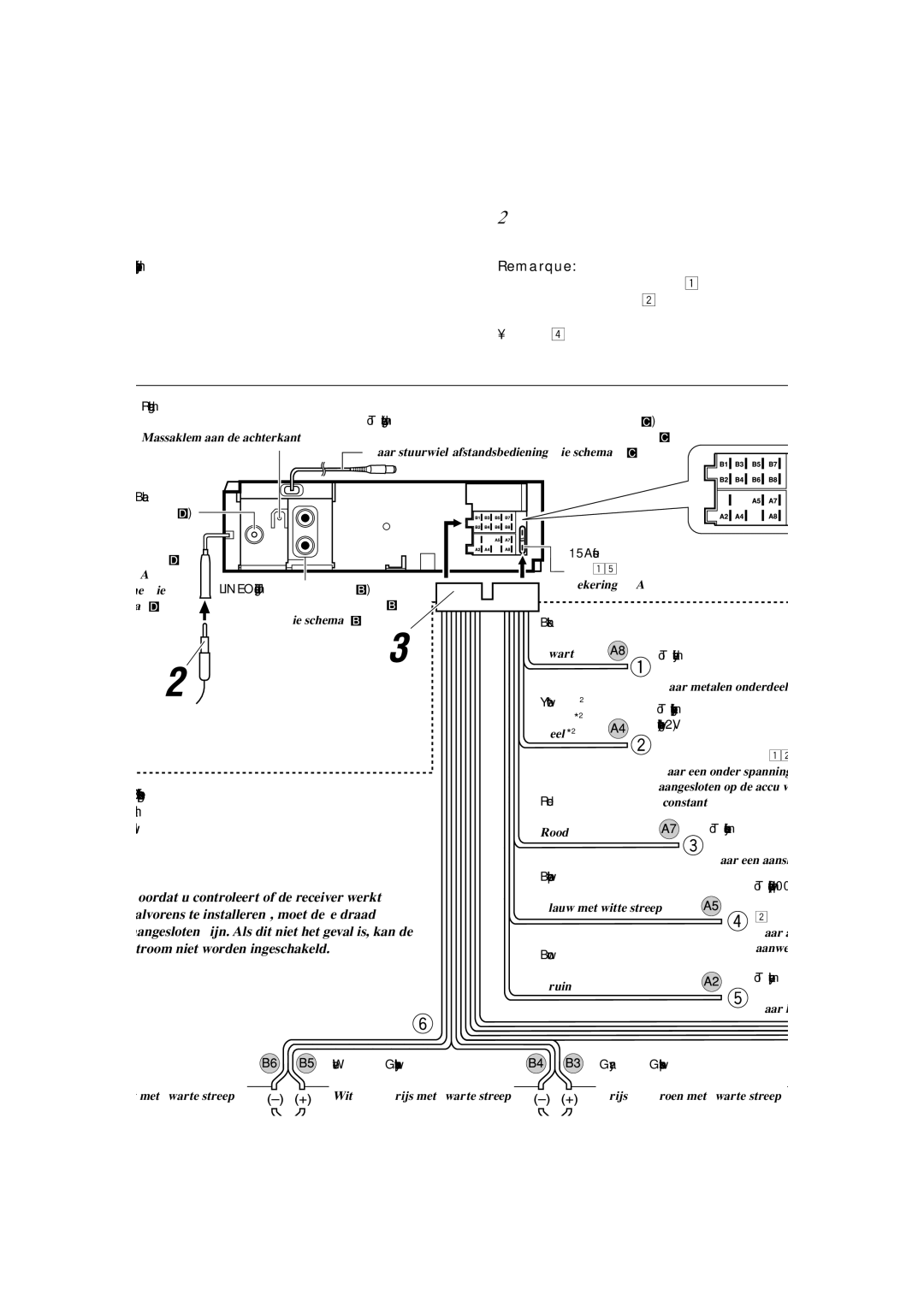
Notes:
•Replace the fuse with one of the specified rating. If the fuse blows frequently, consult your JVC IN-CAR ENTERTAINMENT dealer.
•It is recommended to connect to the speakers with maximum
power of more than 50 W (both at the rear and at the front, with an impedance of 4 Ω to 8 Ω). If the maximum power is less than 50 W, change “AMP GAIN” setting to prevent the speakers from being damaged (see page 24 of the
INSTRUCTIONS).
•To prevent short-circuit, cover the terminals of the UNUSED leads with insulating tape.
•The heat sink becomes very hot after use. Be careful not to touch it when removing this receiver.
Pour éviter tout court-circuit, nous vous recommandons de débrancher la borne négative de la batterie et d’effectuer tous les raccordements électriques avant d’installer l’appareil.
•Assurez-vous de raccorder de nouveau la mise à la masse de cet appareil au châssis de la voiture après l’installation.
Remarques:
•Remplacer le fusible par un de la valeur précisée. Si le fusible saute souvent, consulter votre revendeur d’autoradios JVC.
•Il est recommandé de connecter des enceintes avec une
puissance de plus de 50 W (les enceintes arrière et les enceintes avant, avec une impédance comprise entre 4 Ω et
8 Ω). Si la puissance maximum est inférieure à 50 W, changez le réglage “AMP GAIN” pour éviter d’endommager vos enceintes (voir page 24 du MANUEL D’INSTRUCTIONS).
•Pour éviter les court-circuits, couvrir les bornes des fils qui ne sont PAS UTILISÉS avec de la bande isolante.
•Le dissipateur de chaleur devient très chaud après usage. Faire attention de ne pas le toucher en retirant cet appareil.
Om kortsluiting te voorkomen adviseren wij u om de minpool van de accu los te maken en alle elektrische verbindingen tot stand te brengen voordat u de receiver in de auto installeert.
•Aard dit apparaat beslist weer op het chassis van de auto na het installeren.
Opmerkingen:
•Vervang de zekering door een exemplaar met het aangegeven vermogen. Als de zekering vaak doorslaat, moet u uw JVC car audio dealer raadplegen.
•Sluit bij voorkeur luidsprekers met een hoger maximaal
vermogen dan 50 W (zowel achter als voor, met een impedantie van 4 Ω t/m 8 Ω) aan. Indien het maximale vermogen lager dan 50 W is, moet u “AMP GAIN” in de andere stand stellen zodat de luidsprekers niet kunnen worden beschadigd (zie bladzijde 24 van de GEBRUIKSAANWIJZING).
•Om kortsluiting te voorkomen, moet u de aansluitklemmen van ONGEBRUIKTE gekleurde draden met isolatieband bedekken.
•De warmte-opnemer kan na gebruik erg heet worden. Raak de warmte-opnemer niet aan wanneer u de receiver verwijdert.
Before connecting: Check the wiring in the vehicle carefully. Incorrect connection may cause serious damage to this receiver.
The leads of the power cord and those of the connector from the car body may be different in color.
1Connect the colored leads of the power cord in the order specified in the illustration below.
2Connect the aerial cord.
3Finally connect the wiring harness to the receiver.
Note: If your vehicle does not have any accessory terminal, move the fuse from the fuse position 1 (initial position) to fuse position 2, and connect the red lead (A7) to the positive (+) battery terminal.
• The yellow lead (A4) is not used in this case.
Avant de commencer la connexion: Vérifiez attentivement le câblage du véhicule. Une connexion incorrecte peut endommager sérieusement l’appareil.
Le fil du cordon d’alimentation et ceux des connecteurs du châssis de la voiture peuvent être différents en couleur.
1Connectez les fils colorés du cordon d’alimentation dans l’ordre spécifié sur l’illustration ci-dessous.
2Connectez le cordon d’antenne.
3Finalement, connectez le faisceau de fils à l’appareil.
Remarque: Si votre véhicule ne possède pas de borne accessoire, déplacez le fusible de la position de fusible 1 (position originale) à la position de fusible 2 et connectez le fil rouge (A7) à la borne positive (+) de la batterie.
•Le fil jaune (A4) n’est pas utilisé dans ce cas.
Alvorens aan te sluiten: Controleer de bedrading van de auto zorgvuldig. De receiver kan ernstig worden beschadigd indien u verkeerde verbindingen maakt.
De draden van het stroomsnoer verschillen mogelijk van kleur metde aansluitingen op het chassis van de auto.
1Verbind de gekleurde draden van het stroomsnoer in de afbeelding hieronder aangegeven volgorde.
2Sluit de antenne aan.
3Verbind de draadbundel daarna met de receiver.
Opmerking: Als uw auto niet beschikt over een accessoire- aansluiting, moet u de zekering verplaatsen van stand 1 (beginstand) naar stand 2 en moet u de rode draad (A7) met de pluspool (+) van de accu verbinden.
•In dit geval wordt de gele draad (A4) niet gebruikt.
*2 Before checking the operation of this receiver prior to installation, this lead must be connected, otherwise power cannot be turned on.
*2 Pour vérifier le fonctionnement de cet appareil avant installation, ce fil doit être raccordé, sinon l’appareil ne peut pas être mis sous tension.
*2 Voordat u controleert of de receiver werkt (alvorens te installeren), moet deze draad aangesloten zijn. Als dit niet het geval is, kan de stroom niet worden ingeschakeld.
Yellow*2 | To a live terminal in the fuse block connecting to the car battery (bypassing | | | |
Jaune*2 | | | |
the ignition switch) (constant 12 V) | | | |
Geel*2 | | | |
À une borne sous tension du porte-fusible connectée à la batterie de la voiture | | | |
| | |
| | | |
| (en dérivant l’interrupteur d’allumage) (12 V constant) | | | |
| Naar een onder spanning staande aansluitklem in het zekeringblok die is | | | |
| aangesloten op de accu van de auto (u passeert de contactschakelaar) | | | Fuse block |
Red | (constant 12 V) | | |
| | Porte-fusible |
Rouge | | | |
To an accessory terminal in the fuse block | | | Zekeringblok |
Rood | | |
À une borne accessoire du porte-fusible | | | |
| | | |
| Naar een aansluitklem in het zekeringblok | | | |
Blue with white stripe
| Bleu avec bande blanche | To the remote lead of other equipment or power aerial if any (200 mA max.) |
| Au fil de télécommande de l’autre appareil ou à l’antenne automatique s’il y en a une |
| Blauw met witte streep |
| (200 mA max.) |
| |
| | Naar afstandsbedieningsdraad van andere apparatuur of antenne met circuit indien |
| Brown | aanwezig (200 mA max.) |
| |
| Marron | To cellular phone system |
| Bruin |
| À un système de téléphone cellulaire |
| |
| | Naar het mobiele telefoonsysteem |