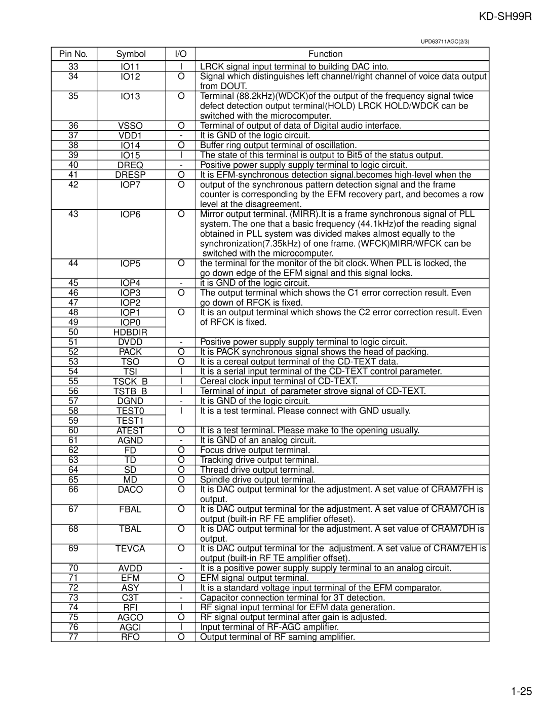
KD-SH99R specifications
The JVC KD-SH99R is an innovative car stereo that exemplifies a blend of advanced technology and user-friendly design, making it a preferred choice for music enthusiasts. This high-performance head unit is known for its impressive audio quality and numerous features that cater to both casual listeners and audiophiles.One of the standout features of the KD-SH99R is its ability to play various media formats, including CDs, MP3, and WMA files. This versatility ensures that users can enjoy their favorite tracks regardless of the medium. The front USB port allows for seamless connectivity with digital devices, giving users the ability to play music directly from USB flash drives. Additionally, the inclusion of an auxiliary input allows for easy connection of smartphones and portable media players, expanding the music options available.
Sound quality is paramount in any car audio system, and the KD-SH99R does not disappoint. It is equipped with a powerful 50 watts per channel output, delivering a robust audio experience that can fill any car interior. The unit features a 3-band parametric equalizer, which allows users to fine-tune their audio settings to achieve the perfect sound that suits their preference. Moreover, the built-in high-pass and low-pass filters offer enhanced control over the frequencies, ensuring that all elements of the music come through clearly.
Another notable feature is the JVC's exclusive K2 Technology, which enhances the quality of compressed audio files, producing a clearer and more dynamic sound. This is particularly beneficial for digital music files which can often lose vibrancy during compression.
For those who value customization, the KD-SH99R offers variable color illumination, allowing users to match the display with their car's interior lighting. This customization is aesthetically pleasing and adds a personal touch to the stereo.
In terms of connectivity, the KD-SH99R is compatible with Bluetooth technology, enabling hands-free calling and wireless music streaming. This feature enhances the driving experience, allowing drivers to stay connected while keeping their focus on the road. The unit also includes AM/FM radio with RDS, providing access to a wide range of radio stations.
In conclusion, the JVC KD-SH99R is a feature-rich car stereo designed to enrich any driving experience. With its high power output, versatile media playback options, advanced sound technologies, and user-friendly design, it stands as an excellent choice for anyone looking to elevate their in-car audio system.
