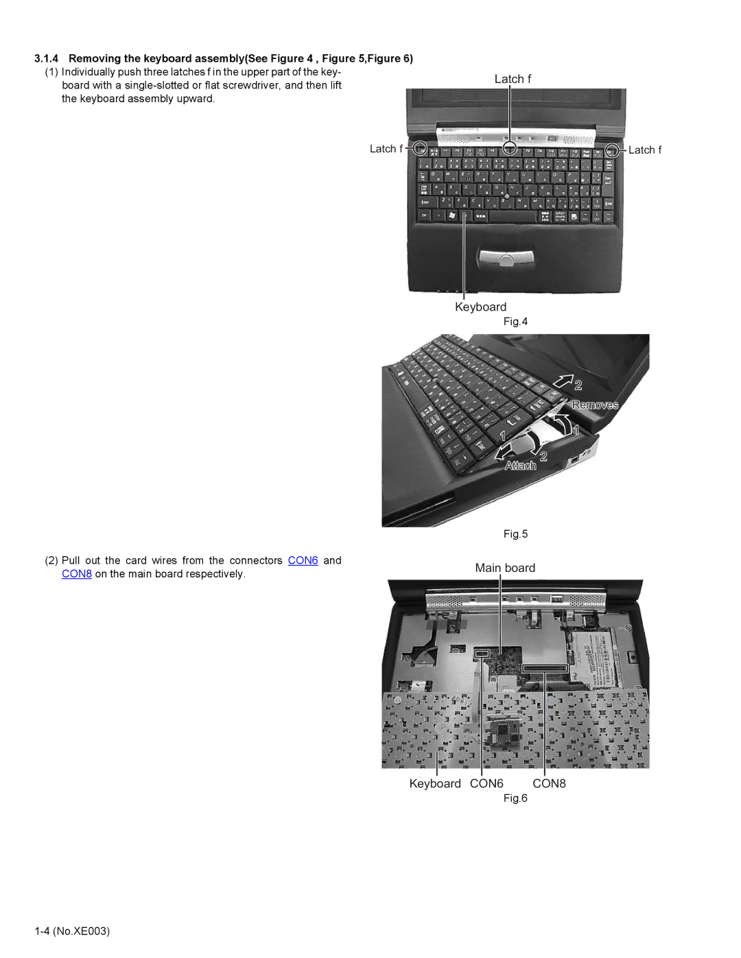
3.1.4Removing the keyboard assembly(See Figure 4 , Figure 5,Figure 6)
(1) Individually push three latches f in the upper part of the key- board with a
Latch f![]()
(2)Pull out the card wires from the connectors CON6 and CON8 on the main board respectively.
Latch f
![]() Latch f
Latch f
Keyboard
Fig.4
![]() 2
2
Removes
1 ![]() 1
1
2
Attach
Fig.5
Main board
Keyboard CON6 | CON8 |
Fig.6
