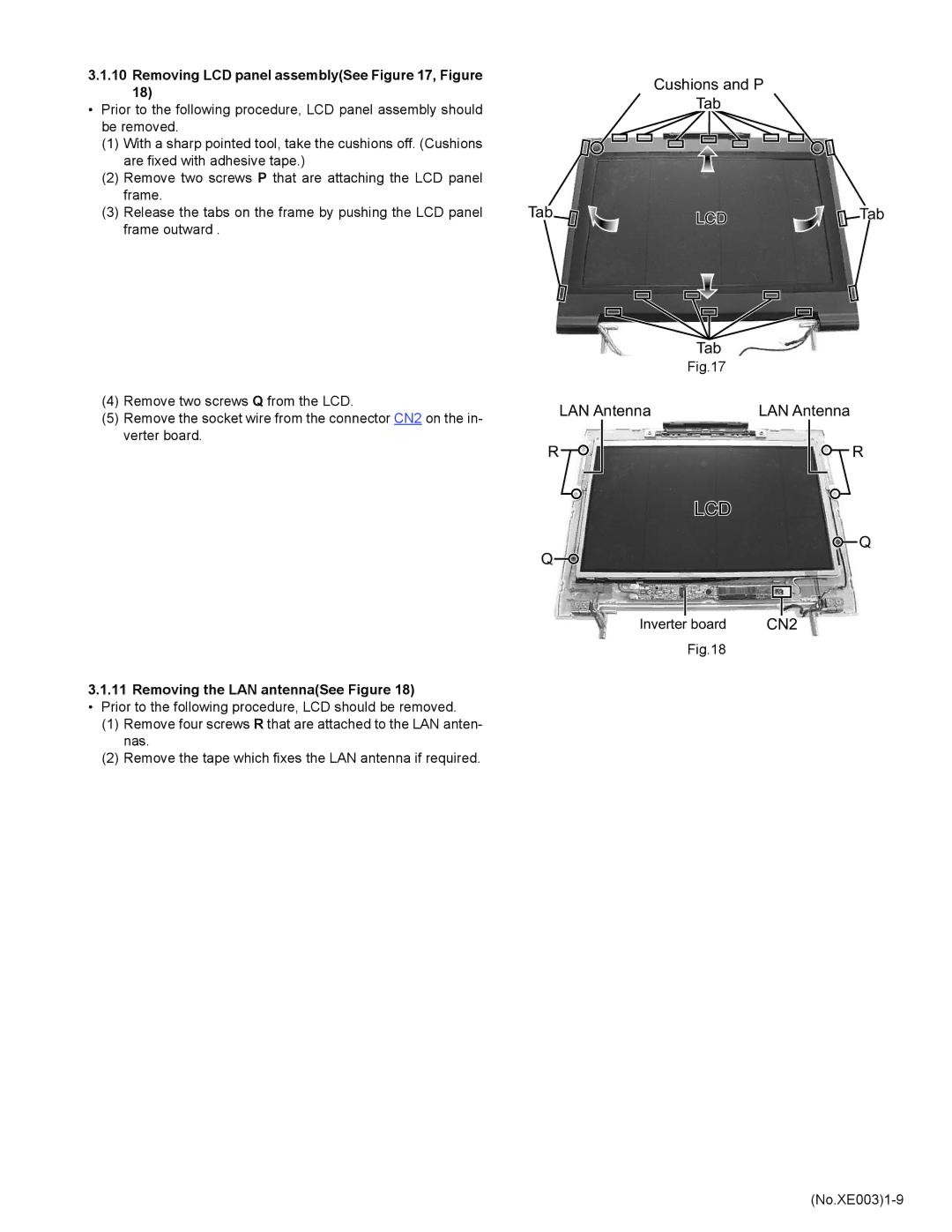
3.1.10Removing LCD panel assembly(See Figure 17, Figure 18)
•Prior to the following procedure, LCD panel assembly should be removed.
(1)With a sharp pointed tool, take the cushions off. (Cushions are fixed with adhesive tape.)
(2)Remove two screws P that are attaching the LCD panel frame.
(3)Release the tabs on the frame by pushing the LCD panel frame outward .
(4)Remove two screws Q from the LCD.
(5)Remove the socket wire from the connector CN2 on the in- verter board.
3.1.11 Removing the LAN antenna(See Figure 18)
•Prior to the following procedure, LCD should be removed.
(1)Remove four screws R that are attached to the LAN anten- nas.
(2)Remove the tape which fixes the LAN antenna if required.
Cushions and P
Tab
Tab | LCD | Tab |
|
|
| Tab |
| Fig.17 |
LAN Antenna | LAN Antenna |
R | R |
LCD
![]() Q
Q
Q![]()
Inverter board | CN2 |
Fig.18