TD-W254 specifications
The JVC TD-W254 is a dual cassette deck that has gained recognition for its reliable performance and high-quality audio playback capabilities. A product of JVC’s decades-long experience in the audio equipment industry, the TD-W254 is designed for both enthusiasts and casual users who appreciate the classic analog sound of cassette tapes.One of the standout features of the TD-W254 is its dual cassette mechanism, which allows for simultaneous playback and recording. This functionality is particularly advantageous for users who enjoy creating mixtapes or transferring music from one tape to another. The deck supports both Type I (normal) and Type II (chrome) cassettes, providing flexibility in terms of sound quality and tape options.
The TD-W254 is equipped with JVC’s innovative Dolby B noise reduction technology, which significantly enhances audio fidelity by reducing background hiss and providing a cleaner listening experience. This technology is particularly beneficial for older cassette tapes, allowing users to enjoy their favorite recordings without excessive noise interference.
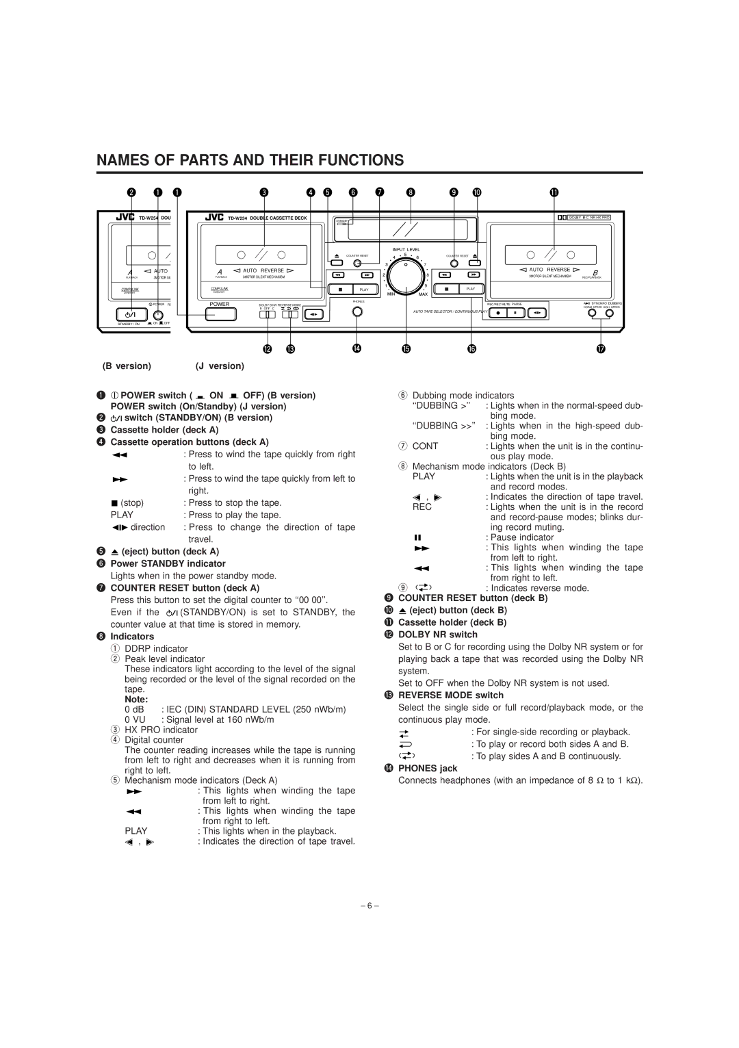
Another notable characteristic of the TD-W254 is its ease of use. The front panel features an intuitive layout with clearly labeled buttons for play, record, pause, and stop functions, making tape operation straightforward even for those less familiar with cassette technology. The deck also includes a built-in LCD display that shows essential information such as playback status and tape direction, providing users with valuable feedback during operation.
In terms of build quality, the JVC TD-W254 is constructed with durability in mind. The chassis is robust, designed to withstand everyday use while maintaining a respectable aesthetic that fits well in any home audio setup. The performance of the deck remains consistent over time, with minimal wear and degradation, ensuring that it continues to deliver quality audio long after its initial purchase.
Overall, the JVC TD-W254 is a versatile cassette deck that caters to a wide range of listening preferences. With its dual cassette functionality, Dolby B noise reduction, user-friendly design, and solid build quality, it stands out as a reliable choice for anyone wanting to relive the analog experience or simply enjoy the nostalgic charm of cassette tapes. Whether for personal enjoyment or as part of a larger audio system, the TD-W254 remains a compelling option in the world of cassette playback.

