Manuals
/
Foundry Networks
/
Computer Equipment
/
Switch
Foundry Networks
LS 648 LEDs, FastIron RPS2-EIF, Port Indicators, System Indicators, LED 1~4
Models:
LS 648
LS 624
1
25
76
76
Download
76 pages
55.7 Kb
22
23
24
25
26
27
28
29
Troubleshooting
Specs
Install
Pinouts and Signaling
Password
Port Indicators
Wiring Map for Serial Cable
Warranty
Dimension
Maintenance
Page 25
Image 25
Page 24
Page 26
Page 25
Image 25
Page 24
Page 26
Contents
Hardware Installation Guide
Foundry FastIron LS Layer 2 Compact Switch
FastIron LS FastIron LS
FGS Release
Copyright 2007 Foundry Networks, Inc. All rights reserved
ABOUT THIS GUIDE
INSTALLING A FASTIRON LS SWITCH
PRODUCT OVERVIEW
CHAPTER
M AINTAINING THE F AST I RON LS H ARDWARE
C HECKING C ONNECTIVITY
C HAPTER
C ONNECTING N ETWORK D EVICES AND
HARDWARE SPECIFICATIONS
APPENDIX A
REGULATORY STATEMENTS
A PPENDIX B
C AUTIONS AND W ARNINGS
C AUTIONS
W ARNINGS
Introduction
Chapter About This Guide
What’s Included in This Edition?
Audience
Warranty Coverage
How to Get Help
Web Access
Email Access
Chapter Product Overview
Hardware Features
FLS624, FLS648
Table 2.1 Chapter Contents
Reset Button
Control Features
Serial Management Interface Console Port
FastIron LS Network Interfaces
FastIron LS 10/100/1000BASE-T Ports
Network Interfaces
Table 2.2 Network Interfaces
Interface
Cable Specifications for New Module
10 Gigabit Ethernet Module Slots
10 Gbps CX4 Ports
10-GbE CX4 Module
CX4 Transceiver Infiniband cable
Port, System and Module Status LEDs
Table 2.3 Port Status LEDs
Condition
System LEDs
Table 2.4 Status LEDs
Optional Redundant Power Supply
Power Supplies
Power Supply Receptacles
Fiber Optic Modules
September
Unpacking a System
Chapter Installing a FastIron LS Switch
Table 3.1 Chapter Contents
General Requirements
Package Contents
Table 3.2 Summary of Installation Tasks
Summary of Installation Tasks
Where to Find More Information
Foundry FastIron Configuration Guide
General Precautions
Installation Precautions
Lifting Precautions
Power Precautions
Installation Location
Preparing the Installation Site
Installing the Device
Cabling Infrastructure
Rack Mount Installation
Desktop Installation
Figure 3.1 Attaching the adhesive feet
Figure 3.3 Installing the device in a rack
Wall Mount Installation
Figure 3.2 Attaching the brackets
About the RPS2-EIF Redundant Power Supply
Installing a Redundant Power Supply
Features and Benefits
Package Contents
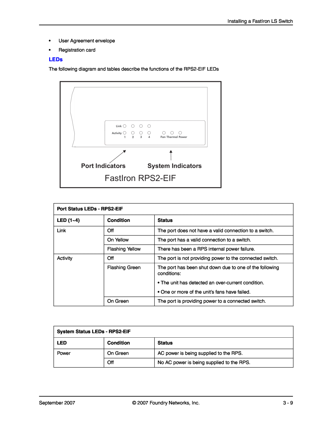
Port Indicators
LEDs
System Indicators
FastIron RPS2-EIF
Equipment Checklist
Installing a FastIron LS Redundant Power Supply
Installation
Mounting
Figure 3.6 Installing the RPS in a Rack
Desktop or Shelf Mounting
Figure 3.5 Attaching the brackets
FastIron LS648
Connecting Switches to the RPS
FLS units
Ports Pin-Out RPS2-EIF
Installing an Optional Module into the Switch
GND N.C RPS Present Status Status Power Good GND
GND N.C
Figure 3.10 Inserting an SFP transceiver into a slot
Installing an SFP Transceiver
Verifying Proper Operation
Powering On the System
Attaching a PC or Terminal
Table 3.3 Serial Cable Wiring
Wiring Map for Serial Cable
Switch’s 9-Pin
Null Modem
September
Assigning Permanent Passwords
Chapter Connecting Network Devices and Checking Connectivity
Table 4.1 Network Connectivity Tasks
Step
FLS648 Switch enable
Recovering from a Lost Password
FLS648 Switch# configure terminal FLS648 Switchconfig#
FLS648 Switchconfig# enable super-user-password text
Devices Running Layer 2 Software
Configuring IP Addresses
Connectors
Connecting Network Devices
Cable Specifications
Connecting to Ethernet or Fast Ethernet Hubs
Connecting a Network Device to a Fiber Port
Connecting to Workstations, Servers, or Routers
Installing a Fiber Optic Module
Automatic MDI/MDIX Detection
Cleaning the Fiber-Optic Connectors
Testing Connectivity
Observing LEDs
Cabling a Fiber Optic Module
Table 4.2 Network Connection-Related LED States
Troubleshooting Network Connections
Desired
Meaning
Foundry FastIron LS Layer 2 Compact Switch Hardware Installation Guide
Using the Temperature Sensor on the FastIron LS
Managing FastIron LS Temperature Settings
Chapter Maintaining the FastIron LS Hardware
Table 5.1 Chapter Contents
Displaying Syslog Messages for Temperature on the FastIron LS
Displaying the Temperature on the FastIron LS
FLS648 Switch show chassis Power supply 1 not present
Power supply 2 NA - AC - Regular present, status ok Fan 1 failed
FLS648 Switch# show log
Installing or Replacing a 10-Gigabit Ethernet Module
Hardware Maintenance Schedule
Displaying Management Module CPU Usage
Changing the Temperature Polling Interval
Replacing a Fiber Optic Module
Installing an Optional Module into the Switch
Removing a 10-Gigabit Ethernet Module
Removing a Fiber Optic Module
Installing a New Fiber Optic Module
Bail Latch
Cabling a Fiber Optic Module
Cleaning the Fiber-Optic Connectors
Digital Optical Monitoring
Table 5.2 Status Value Description
Supported Media
Status Value
no optical-monitor alarm interval
CLI Commands
show optic port/slotnumber
September
Diagnosing Switch Indicators
Chapter Troubleshooting
Table 0.1 Troubleshooting Chart
Symptom
Installation
Power and Cooling Problems
In-Band Access
Table 0.2 Chapter Contents
Chapter Hardware Specifications
FastIron LS specifications
Redundant Power supply specifications
Physical Dimensions
FastIron LS Specifications
Environmental Considerations
Operating Environment
Storage Environment
Cooling
Mean Time Before Failure
Table 0.7 Storage Environment
Table 0.10 Fan Noise Levels for FastIron LS 48-Port Switch
Table 0.9 Fan Noise Levels for FastIron LS 24-Port Switch
Chassis side
Fan Speed
FCC CFR 47 Part 15 Warning
Regulatory Compliance
CISPR 22 CLASS A Warning
Table 0.11 Regulatory Compliance and Safety Approvals Certifications
Pinouts and Signaling
Warranty
VCCI
Serial Console Port Pinouts
LC connector for
Connector Type
Table 0.12 Cable length summary table
Cable Type1
Cable Type
Table 0.12 Cable length summary table Continued
Specifications
AC Power Supply
Table 0.13 Specifications for AC Power
Property
Power Cords
Redundant Power Supply Specifications
Key features
Physical Dimensions and Weight
Electromagnetic Compatibility EMC and Immunity Standards
Input Connector
Table 0.15 Input Connector for Power Supplies
Input Connector Properties
Safety Warnings
Safety Agency Approvals and Certifications
Environmental Considerations
Table 0.17 Safety Warning Labels on Power Supplies
Input specifications
Electrical Specifications
Table 0.20 Input Specifications for Power Supplies
Table 0.19 Mean Time Before Failure Specifiations
September
U.S.A
Appendix A Regulatory Statements
Industry Canada Statement
Europe and Australia
September
Cautions
Appendix B Cautions and Warnings
Foundry FastIron LS Layer 2 Compact Switch Hardware Installation Guide
Cautions and Warnings CAUTION Never leave tools inside the device
Warnings
Page
Foundry FastIron LS Layer 2 Compact Switch Hardware Installation Guide
Top
Page
Image
Contents