Installation and Connection
Mounting the Housing to the Wall (continued)
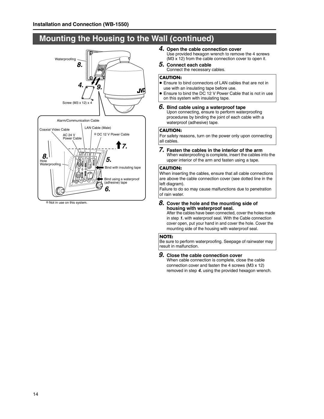
Waterproofing
8.
4. ![]()
![]() 9.
9.
Screw (M3 x 12) x 4
Alarm/Communication Cable
Coaxial Video Cable | LAN Cable (Male) |
| |
AC 24 V | T DC 12 V Power Cable |
Power Cable |
|
| 7. |
4. Open the cable connection cover
Use provided hexagon wrench to remove the 4 screws (M3 x 12) from the cable connection cover to open it.
5. Connect each cable
Connect the necessary cables.
CAUTION:
●Ensure to bind connectors of LAN cables that are not in use with an insulating tape before use.
●Ensure to bind the DC 12 V Power Cable that is not in use on this system with insulating tape.
6. Bind cable using a waterproof tape
Upon connecting, ensure to perform waterproofing procedures by binding the joint of each cable with a waterproof (adhesive) tape.
CAUTION:
For safety reasons, turn on the power only upon connecting all cables.
7. Fasten the cables in the interior of the arm
8.
Hole Waterproofing
5. |
Bind with insulating tape |
Bind using a waterproof |
(adhesive) tape |
6. |
When waterproofing is complete, insert the cables into the upper interior of the arm and fasten using a tape.
CAUTION:
When inserting the cables, ensure that all cable connections are above the cable connection cover (see dotted line in the left diagram).
Failure to do so may cause malfunctions due to penetration of rain water.
T Not in use on this system.
8. Cover the hole and the mounting side of housing with waterproof seal.
After the cables have been connected, cover the holes made in step 1. with waterproof seal. With the Cable connection cover open, put your hand in and cover the hole. Cover the mounting side of the housing with waterproof seal.
NOTE:
Be sure to perform waterproofing. Seepage of rainwater may result in malfunction.
9. Close the cable connection cover
When cable connection is complete, close the cable connection cover and fasten the 4 screws (M3 x 12) removed in step 4. using the provided hexagon wrench.
14