System Example
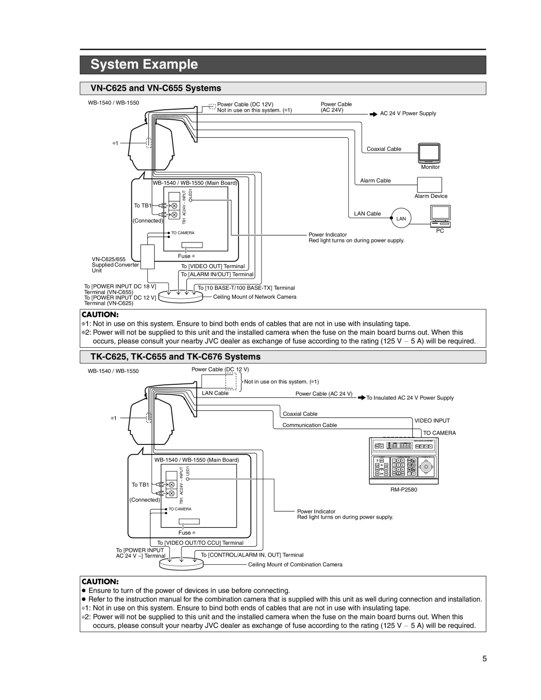
VN-C625 and VN-C655 Systems
Power Cable (DC 12V) | Power Cable |
| |
| Not in use on this system. (T1) | (AC 24V) | AC 24 V Power Supply |
|
|
| |
T1 |
|
| Coaxial Cable |
|
|
| |
|
|
| Monitor |
|
| Alarm Cable | |
|
|
|
To TB1
(Connected)
INPUT | LED1 |
AC24V ~ |
|
TB1 |
|
Alarm Device
LAN Cable
LAN
TO CAMERA |
Power Indicator
PC
Red light turns on during power supply.
Fuse T
Supplied ConverterTo [VIDEO OUT] Terminal
Unit
To [ALARM IN/OUT] Terminal
To [POWER INPUT DC 18 V] | To [10 |
Terminal | Ceiling Mount of Network Camera |
To [POWER INPUT DC 12 V] | |
Terminal |
|
CAUTION:
T1: Not in use on this system. Ensure to bind both ends of cables that are not in use with insulating tape.
T2: Power will not be supplied to this unit and the installed camera when the fuse on the main board burns out. When this occurs, please consult your nearby JVC dealer as exchange of fuse according to the rating (125 V - 5 A) will be required.
TK-C625, TK-C655 and TK-C676 Systems
Power Cable (DC 12 V) | ||
|
| |
|
| Not in use on this system. (T1) |
| LAN Cable | Power Cable (AC 24 V) |
| To Insulated AC 24 V Power Supply | |
T1 | Coaxial Cable | |
VIDEO INPUT | ||
| ||
| Communication Cable | |
| TO CAMERA |
|
|
|
| |
LENS |
| CAMERA/POSITION | PAN/TILT | |
| 1 | 2 | 3 |
|
IRIS | 4 | 5 | 6 |
|
To TB1
(Connected)
INPUT | LED1 |
AC24V ~ |
|
TB1 |
|
![]() TO CAMERA
TO CAMERA
Fuse T
FOCUS | 7 | 8 | 9 |
AF | |||
ZOOM |
| 0 |
|
Power Indicator
Red light turns on during power supply.
To [VIDEO OUT/TO CCU] Terminal
To [POWER INPUT | To [CONTROL/ALARM IN, OUT] Terminal | ||
AC 24 V ~] Terminal | |||
|
|
| Ceiling Mount of Combination Camera |
|
|
| |
CAUTION:
●Ensure to turn of the power of devices in use before connecting.
●Refer to the instruction manual for the combination camera that is supplied with this unit as well during connection and installation. T1: Not in use on this system. Ensure to bind both ends of cables that are not in use with insulating tape.
T2: Power will not be supplied to this unit and the installed camera when the fuse on the main board burns out. When this occurs, please consult your nearby JVC dealer as exchange of fuse according to the rating (125 V - 5 A) will be required.
5