Installation and Connection
Disassembling the Housing
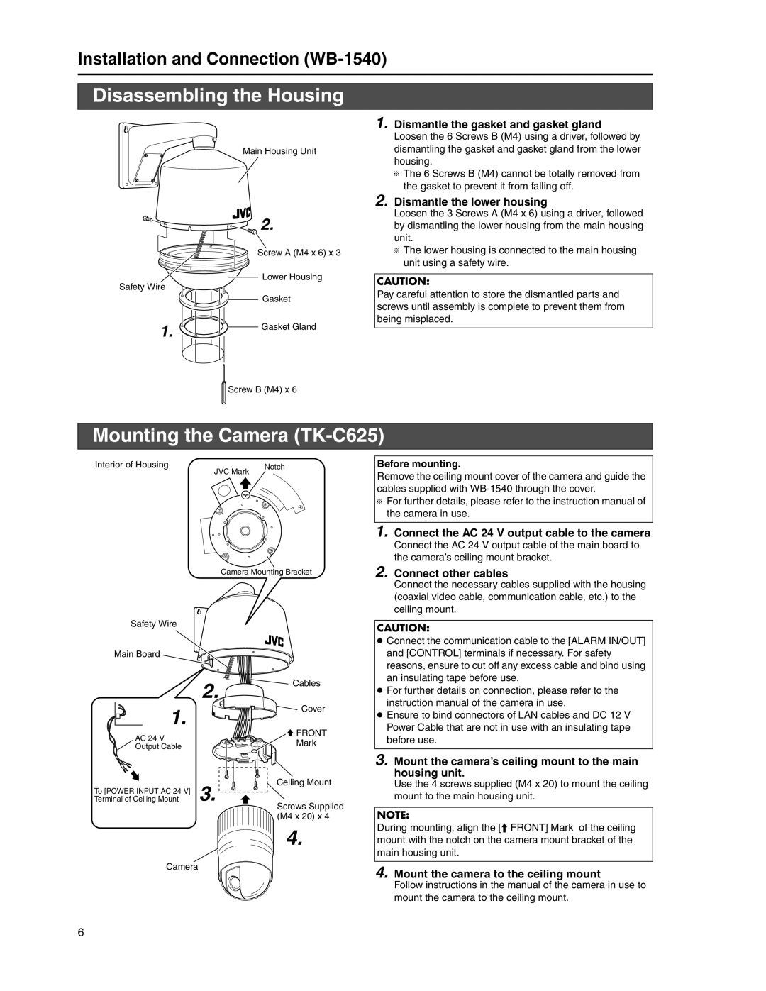
Main Housing Unit
2.
Screw A (M4 x 6) x 3
Lower Housing
Safety Wire
Gasket
1.![]() Gasket Gland
Gasket Gland
Screw B (M4) x 6
1. Dismantle the gasket and gasket gland
Loosen the 6 Screws B (M4) using a driver, followed by dismantling the gasket and gasket gland from the lower housing.
TThe 6 Screws B (M4) cannot be totally removed from the gasket to prevent it from falling off.
2.Dismantle the lower housing
Loosen the 3 Screws A (M4 x 6) using a driver, followed by dismantling the lower housing from the main housing unit.
TThe lower housing is connected to the main housing unit using a safety wire.
CAUTION:
Pay careful attention to store the dismantled parts and screws until assembly is complete to prevent them from being misplaced.
Mounting the Camera (TK-C625)
Interior of Housing | JVC Mark | Notch |
|
|
Camera Mounting Bracket
Before mounting.
Remove the ceiling mount cover of the camera and guide the cables supplied with
TFor further details, please refer to the instruction manual of the camera in use.
1. Connect the AC 24 V output cable to the camera
Connect the AC 24 V output cable of the main board to the camera’s ceiling mount bracket.
2. Connect other cables
Safety Wire
Main Board
2. ![]()
![]() Cables
Cables
1.![]()
![]()
![]() Cover
Cover
AC 24 V |
| FRONT |
| Mark | |
Output Cable |
| |
|
| |
To [POWER INPUT AC 24 V] | 3. | Ceiling Mount |
| ||
Terminal of Ceiling Mount | Screws Supplied | |
|
| |
|
| (M4 x 20) x 4 |
4.
Camera
Connect the necessary cables supplied with the housing (coaxial video cable, communication cable, etc.) to the ceiling mount.
CAUTION:
●Connect the communication cable to the [ALARM IN/OUT] and [CONTROL] terminals if necessary. For safety reasons, ensure to cut off any excess cable and bind using an insulating tape before use.
●For further details on connection, please refer to the instruction manual of the camera in use.
●Ensure to bind connectors of LAN cables and DC 12 V Power Cable that are not in use with an insulating tape before use.
3. Mount the camera’s ceiling mount to the main housing unit.
Use the 4 screws supplied (M4 x 20) to mount the ceiling mount to the main housing unit.
NOTE:
During mounting, align the [D FRONT] Mark of the ceiling mount with the notch on the camera mount bracket of the main housing unit.
4. Mount the camera to the ceiling mount
Follow instructions in the manual of the camera in use to mount the camera to the ceiling mount.
6