Consists of XV-THV70R, SP-PWV70, SP-XSV70, and SP-XCV70
TH-V70R
If in Doubt Consult a Competent Electrician
Important for Laser Products
Above ALL
Page
Table of Contents
Safety precautions
Checking the supplied accessories
Introduction
Important cautions
Center unit
Names of parts and controls
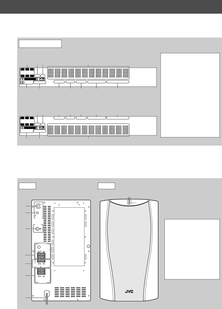
Front panel
Rear panel
Front Powered subwoofer
Powered subwoofer
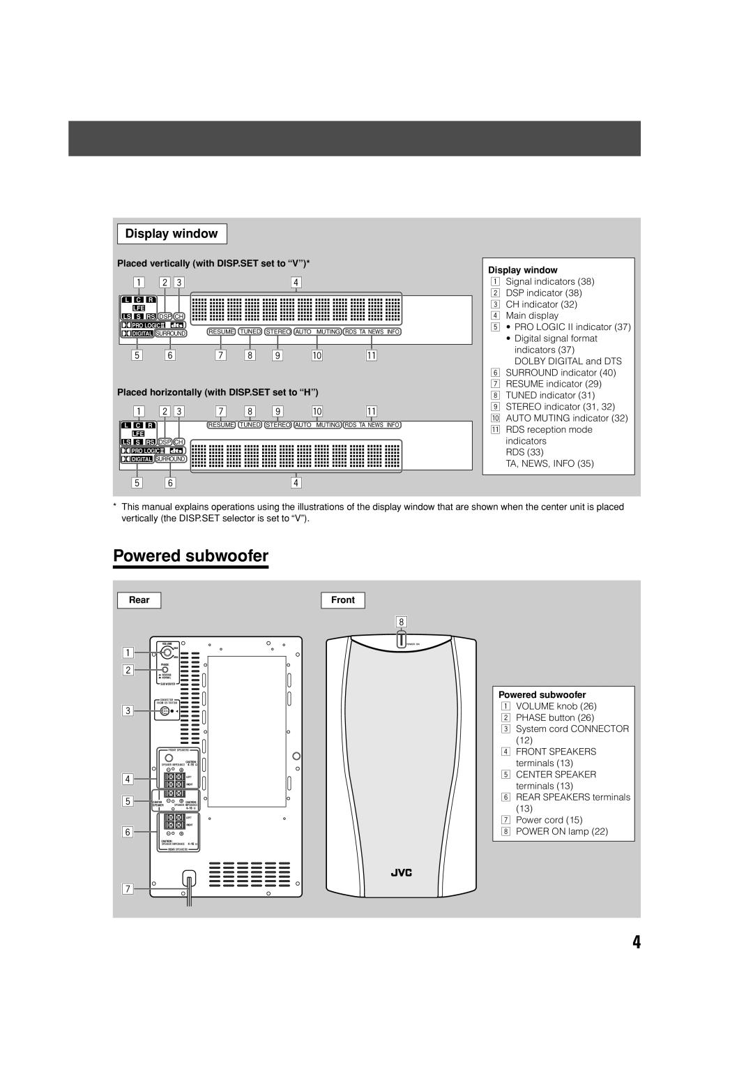
Display window
Display window
Remote control
Remote control
Names of parts and controls
Playable disc types
About discs
PAL
ALL
About discs
High-resolution still image display
Disc structure
Playback Control function PBC
When placing the center unit vertically
Setting the DISP.SET selector
When placing the center unit Horizontally
Getting started
Getting started
When placing the center unit vertically
Attach the legs to the stand
For connections, see pages 10 to
To connect a TV without the Scart connector
Connecting a TV
To connect a TV with the Scart connector
Connections
Connecting the FM and AM MW antennas
AM MW loop antenna
FM antenna
Connecting the satellite speakers
Connecting the powered subwoofer
Powered subwoofer
Speaker layout
Before connecting the speaker cord
Connecting the satellite front, center, rear speakers
Connecting the speaker cord to the satellite speakers
Connecting the speaker cord to the powered subwoofer
Connecting to an analog component
Connecting to a digital component
RCA pin plug cord To audio output
Connecting the power cord
When attaching the rear speakers to a wall
Installing the equipment on the wall
When attaching the AM MW loop antenna to a wall
Attaching speakers to the brackets
Example of attachment
When attaching the center unit to a wall
Page
Putting batteries in the remote control
Using the remote control
Operating the system from the remote control
Replace the cover
Setting the remote control signal for operating your TV
Using the remote control for TV operations
Release TV
Try to operate your TV by pressing TV
Press Audio to turn the power on Press to turn the power on
Basic operations
Turning on/off the system
Adjusting volume
Press Volume + or -. Press VOL + or
Selecting the source to play
Basic operations
To restore the sound
Turning off the sound temporarily
Press Muting
Turning off the power with the timer
Adjusting the brightness
Press Dimmer
Press Sleep
Subwoofer +
Changing the decode mode
Volume control
Setting the subwoofer
Turn Volume knob
Phase setting
Basic playback
When the center unit is placed horizontally, press
Inserting and removing a disc
Preventing screen burn-out with the screen saver
Stopping playback temporarily
Stopping playback completely
Basic playback
Moving back the playback position during DVD playback
Starting playback again
Locating a desired selection using Number buttons
Searching for a particular point
Locating the beginning of a desired chapter or track
Using preset tuning
Tuning in to stations manually
To store the preset stations
Tuner operations
Selecting the FM reception mode
To tune in to a preset station
Reducing the noise of AM MW broadcast
What information can RDS signals provide?
Using the RDS Radio Data System to receive FM stations
To show the RDS signals
Tuner operations
Searching for a program by PTY codes
To search for a program using the PTY codes
Press PTY Search while listening to an FM station
PTY Search
Test
Switching to broadcast program of your choice temporarily
TA/NEWS/INFO
TA News Info TA/NEWS TA/INFO
Case
How the Enhanced Other Network function actually works
Creating the realistic sound fields
Digital signal format indicators on the display window
Dolby Surround
DTS Digital Surround
DAP Digital Acoustic Processor modes All Channel Stereo
Available Surround modes for each input signal
All Channel Stereo reproduction
Creating sound field
Creating the realistic sound fields
Selecting the surround mode
Adjust the speaker output levels -10 dB to +10 dB
Using DAP Modes and All Channel Stereo
Adjust the speakers output levels -10 dB to +10 dB
Press Test again to stop the test tone
Contents of the on-screen bar
Using the on-screen bar
Advanced operations
Showing the on-screen bar
Changing the time information
Basic operation through the on- screen bar
Press on Screen twice
Press Cursor ∞/5 to select the desired option
Locating a desired scene from the disc menu
Advanced operations
Locating a desired scene from the DVD menu
Press TOP Menu or Menu
Selecting a view angle
Selecting a view angle of DVD
Press Angle
Press Angle repeatedly to select the desired view angle
Changing the subtitle languages and audio languages
Showing all view angles on the TV
Selecting the subtitle language
Press Audio
Selecting the audio language
Press Audio repeatedly to select the desired audio language
On-screen bar appears on the TV screen
Press Cursor ∞/5 to select the desired audio language
Selecting the audio channel
Press Audio repeatedly to select the desired audio channel
ST 1 ST 2 L 1 R 1 L 2 R
Locating a desired chapter from the on-screen bar
Playing from a specified position on a disc
Press Cursor ∞/5 to select the desired audio channels
Cursor and Enter button
Locating a desired scene from the digest display
Locating a desired position by specifying the time
Use Number buttons 0-9 to enter the time
Press Digest
Special picture playback
Frame-by-frame playback
Showing continuous still pictures
Zooming in/out
Playing back in slow-motion
Press ¡ or
Press Zoom + or
Press Cursor 3/2 repeatedly to select the VFP mode
Changing the VFP setting
To adjust User 1 or User
Repeat steps 2-5 to adjust other parameters
Playing back in the desired order
Changing the track order
Playing back tracks in random order
Repeat to program the next steps
Repeat playback
Press Cursor ∞/5 repeatedly to select the repeat mode
Repeating a current title, chapter, or all tracks
Repeating a desired part
Basic operations
MP3 disc playback
Insert an MP3 disc
As many times as required
MP3 control display
Operations through the MP3 control display
01 / 14 Total
Operations
Slide-show
Jpeg disc playback
Insert a Jpeg disc
Press Zoom + or while the slide-show is paused. See also
Jpeg control display
Operations through the Jpeg control display
Press Number buttons 0-10, +10 to enter the file number
Press Menu
Setting DVD preferences
Using the choice menus
Choice menus
Basic procedure through the choice menus
Desired option
Choice button
Language codes list
Setting DVD preferences
Items Contents and guidelines
Language menu
Monitor Type
Picture menu
Screen Saver
MP3/JPEG
Audio menu
Size menu
SPK. Setting menu
Distance menu
Level menu
Others menu
Restricting playback by Parental Lock
Setting Parental Lock
Choice
Cursor Enter buttons
Press Number buttons 0-9 to enter your password
Changing the setting of Parental Lock
New setting is stored
Releasing Parental Lock temporarily
Country/Area codes list for Parental Lock
Press Setting
Setting the system through the display window
Press Cursor 2/3 to make an adjustment
Repeat steps 2 and 3 to set other items
Operating other manufacturers’ VCR
Setting the remote control signal for operating your
Release VCR
Try to operate your VCR by pressing VCR
Cleaning the system
Maintenance
General Notes
Handling Discs
General
Troubleshooting
DVD Playback
MP3 Playback
Troubleshooting
Jpeg Playback
Others
Refers to individual chapters included in a title
Glossary
Specifications
Front/Center/Rear
Amplifier section
At 1 kHz, with 10 %
Total harmonic distortion
0402TMMMDWJEM