Device elements
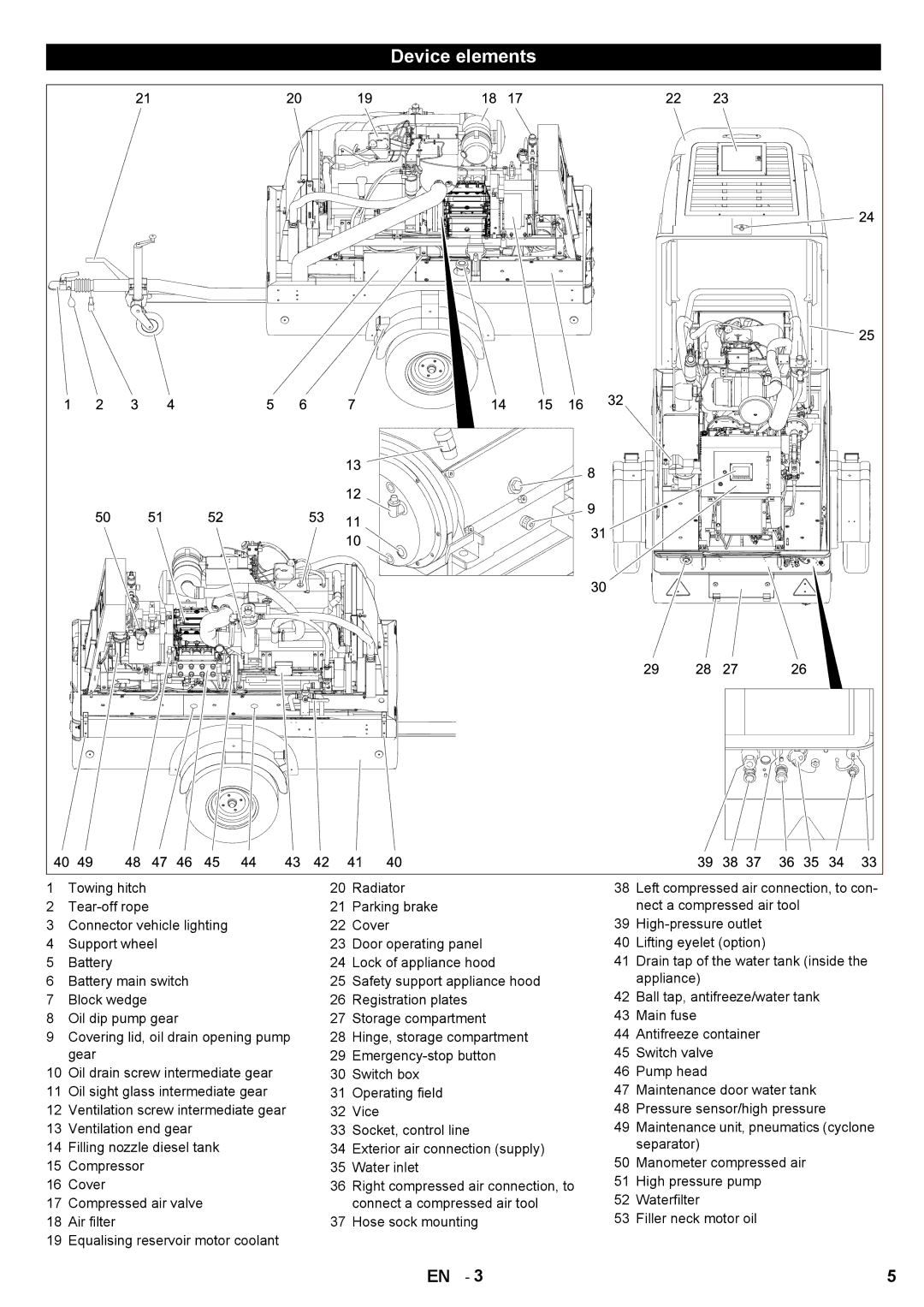
1 | Towing hitch | 20 | Radiator | 38 | Left compressed air connection, to con- |
2 | 21 | Parking brake |
| nect a compressed air tool | |
3 | Connector vehicle lighting | 22 | Cover | 39 | |
4 | Support wheel | 23 | Door operating panel | 40 | Lifting eyelet (option) |
5 | Battery | 24 | Lock of appliance hood | 41 | Drain tap of the water tank (inside the |
6 | Battery main switch | 25 | Safety support appliance hood |
| appliance) |
7 | Block wedge | 26 | Registration plates | 42 | Ball tap, antifreeze/water tank |
8 | Oil dip pump gear | 27 | Storage compartment | 43 | Main fuse |
9 | Covering lid, oil drain opening pump | 28 | Hinge, storage compartment | 44 | Antifreeze container |
| gear | 29 | 45 | Switch valve | |
10 | Oil drain screw intermediate gear | 30 | Switch box | 46 | Pump head |
11 | Oil sight glass intermediate gear | 31 | Operating field | 47 | Maintenance door water tank |
12 | Ventilation screw intermediate gear | 32 | Vice | 48 | Pressure sensor/high pressure |
13 | Ventilation end gear | 33 | Socket, control line | 49 | Maintenance unit, pneumatics (cyclone |
14 | Filling nozzle diesel tank | 34 | Exterior air connection (supply) |
| separator) |
15 | Compressor | 35 | Water inlet | 50 | Manometer compressed air |
16 | Cover | 36 | Right compressed air connection, to | 51 | High pressure pump |
17 | Compressed air valve |
| connect a compressed air tool | 52 | Waterfilter |
18 | Air filter | 37 | Hose sock mounting | 53 | Filler neck motor oil |
19 | Equalising reservoir motor coolant |
|
|
|
|
|
|
| EN - 3 |
| 5 |