Installation
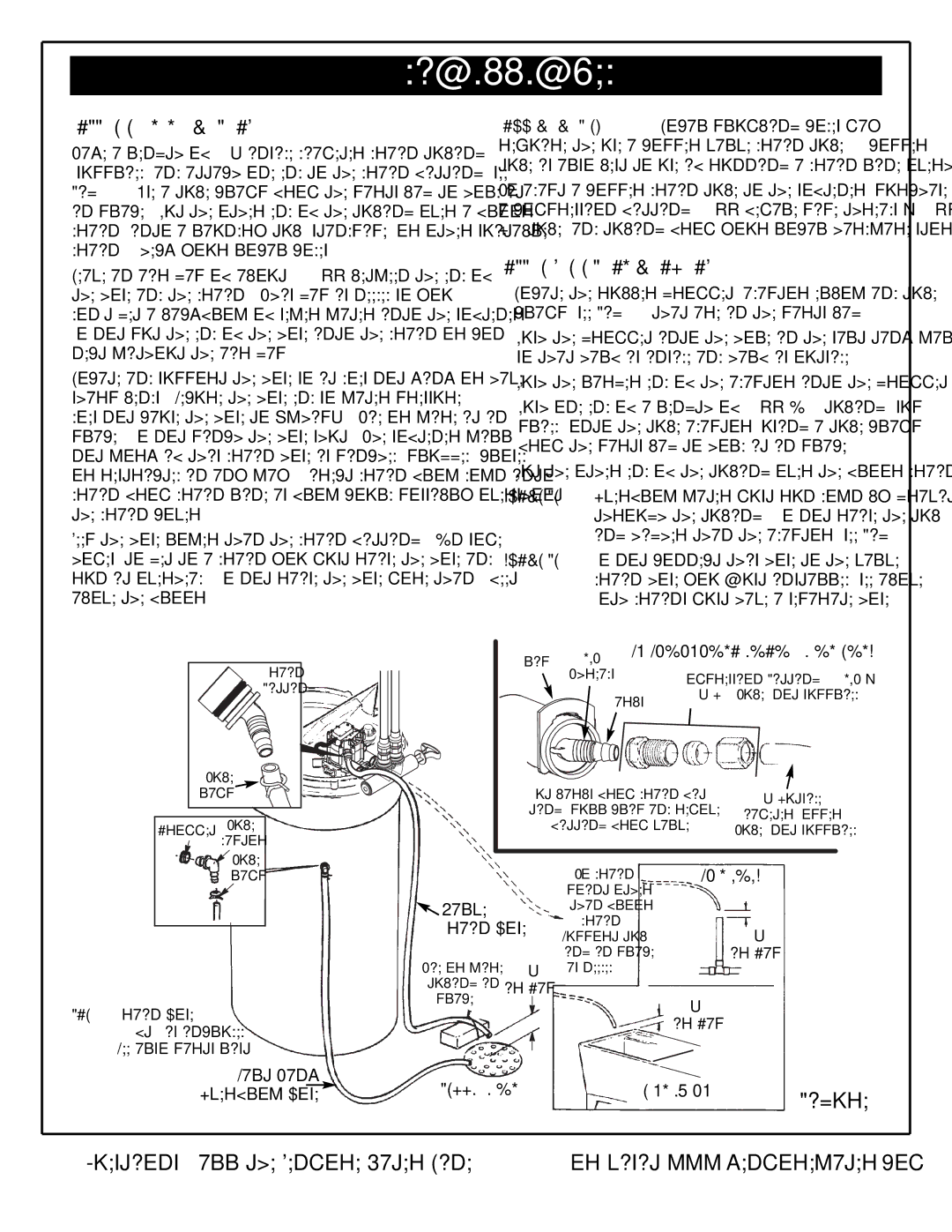
CONNECT THE VALVE DRAIN HOSE |
| COPPER DRAIN TUBE: Local plumbing codes may | |||||
Take a length of 3/8” inside diameter drain tubing |
| require the use a copper valve drain tube. A copper | |||||
(supplied) and attach one end to the drain fitting (see |
| tube is also best to use if running a drain line overhead. | |||||
Fig. 11). Use a tube clamp from the parts bag to hold it | To adapt a copper drain tube to the softener, purchase | ||||||
in place. Put the other end of the tubing over a floor |
| a compression fitting (1/4'' female pipe threads x 1/2'' | |||||
drain, into a laundry tub, standpipe, or other suitable |
| O.D. tube) and tubing from your local hardware store. | |||||
drain. Check your local codes. |
| CONNECT SALT TANK OVERFLOW HOSE | |||||
Leave an air gap of about |
| ||||||
the hose and the drain. This gap is needed so you |
| 1. | Locate the rubber grommet, adaptor elbow and tube | ||||
don’t get a backflow of sewer water into the softener. |
| 2. | clamp (see Fig. 11) that are in the parts bag. | ||||
Do not put the end of the hose into the drain or con- |
| Push the grommet into the hole in the salt tank wall | |||||
nect without the air gap. |
| 3. | so that half is inside and half is outside. |
| |||
Locate and support the hose so it does not kink or have | Push the larger end of the adaptor into the grommet. | ||||||
sharp bends. Secure the hose end so water pressure |
| 4. Push one end of a length of 3/8'' I.D. tubing (sup- | |||||
does not cause the hose to “whip”. Tie or wire it in |
| ||||||
|
| plied) onto the tube adaptor, using a tube clamp | |||||
place. Do not pinch the hose shut. The softener will |
|
| |||||
|
| from the parts bag to hold it in place. |
| ||||
not work if this drain hose is pinched, plugged, closed |
|
|
| ||||
| 5. Put the other end of the tubing over the floor drain. | ||||||
or restricted in any way. Direct drain flow down into |
| ||||||
drain from drain line as flow could possibly overshoot |
| IMPORTANT: Overflow water must run down by gravity | |||||
the drain cover. |
|
|
|
| through the tubing. Do not raise the tub- | ||
Keep the hose lower than the drain fitting. In some |
|
|
| ing higher than the adaptor (see Fig. 11). | |||
homes, to get to a drain you must raise the hose and |
| IMPORTANT: Do not connect this hose to the valve | |||||
run it overhead. Do not raise the hose more than 8 feet |
|
| drain hose you just installed (see above). | ||||
above the floor. |
|
|
|
| Both drains must have a separate hose. | ||
| Drain |
|
| Clip | 1/4 NPT SUBSTITUTING RIGID DRAIN LINE | ||
|
|
|
| Threads | Compression Fitting, 1/4 NPT x | ||
| Fitting |
|
|
| Barbs | 1/2” O.D. Tube (not supplied) | |
|
|
|
|
|
|
| |
Tube |
|
| Cut barbs from drain fit- | 1/2” Outside | |||
Clamp |
|
| |||||
Grommet | Tube |
|
| ting (pull clip and remove | Diameter Copper | ||
|
|
| fitting from valve) | Tube (not supplied) | |||
| Adaptor |
|
|
|
|
|
|
| Tube |
|
|
| To drain | STANDPIPE |
|
| Clamp |
|
|
|
| ||
|
| Valve |
|
| point other |
|
|
|
|
|
| than floor |
|
| |
|
| Drain Hose | drain. |
| |||
|
| Support tub- |
| ||||
| Tie or wire | ing in place | Air Gap |
| |||
| as needed. |
|
| ||||
| tubing in | Air Gap |
| ||||
NOTE: Drain Hose | place |
|
|
| |||
|
|
|
| Air Gap |
| ||
(20 ft.) is included. |
|
|
|
| |||
See also parts list. |
|
|
|
|
|
| |
| Salt Tank | FLOOR DRAIN | LAUNDRY TUB | Figure 11 | |||
Overflow Hose | |||||||
Questions? Call the Kenmore Water Line
10
