Service Information
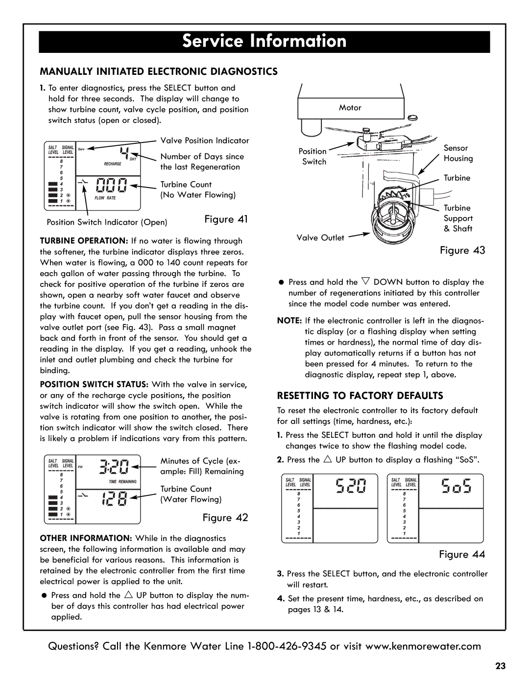
MANUALLY INITIATED ELECTRONIC DIAGNOSTICS
1. To enter diagnostics, press the SELECT button and |
|
| ||
hold for three seconds. The display will change to | Motor |
| ||
show turbine count, valve cycle position, and position |
| |||
switch status (open or closed). |
|
|
| |
Valve Position Indicator | Position | Sensor | ||
Number of Days since | ||||
Switch | Housing | |||
the last Regeneration |
| Turbine | ||
Turbine Count |
| |||
(No Water Flowing) |
| Turbine | ||
Position Switch Indicator (Open) | Figure 41 |
| ||
| Support | |||
TURBINE OPERATION: If no water is flowing through | Valve Outlet | & Shaft | ||
Figure 43 | ||||
the softener, the turbine indicator displays three zeros. |
| |||
When water is flowing, a 000 to 140 count repeats for |
|
| ||
each gallon of water passing through the turbine. To | = Press and hold the s DOWN button to display the | |||
check for positive operation of the turbine if zeros are | ||||
shown, open a nearby soft water faucet and observe | number of regenerations initiated by this controller | |||
the turbine count. If you don’t get a reading in the dis- | since the model code number was entered. | |||
play with faucet open, pull the sensor housing from the | NOTE: If the electronic controller is left in the diagnos- | |||
valve outlet port (see Fig. 43). Pass a small magnet | tic display (or a flashing display when setting | |||
back and forth in front of the sensor. You should get a | times or hardness), the normal time of day dis- | |||
reading in the display. If you get a reading, unhook the | play automatically returns if a button has not | |||
inlet and outlet plumbing and check the turbine for | been pressed for 4 minutes. To return to the | |||
binding. |
| diagnostic display, repeat step 1, above. | ||
POSITION SWITCH STATUS: With the valve in service, | RESETTING TO FACTORY DEFAULTS | |||
or any of the recharge cycle positions, the position | ||||
switch indicator will show the switch open. | While the | To reset the electronic controller to its factory default | ||
valve is rotating from one position to another, the posi- | for all settings (time, hardness, etc.): |
| ||
tion switch indicator will show the switch closed. There | 1. Press the SELECT button and hold it until the display | |||
is likely a problem if indications vary from this pattern. | ||||
|
| changes twice to show the flashing model code. | ||
Minutes of Cycle (ex- | 2. Press the r UP button to display a flashing “SoS”. | |||
ample: Fill) Remaining |
|
| ||
Turbine Count |
|
| ||
(Water Flowing) |
|
| ||
| Figure 42 |
|
| |
OTHER INFORMATION: While in the diagnostics |
|
| ||
screen, the following information is available and may |
| Figure 44 | ||
be beneficial for various reasons. This information is |
| |||
retained by the electronic controller from the first time | 3. Press the SELECT button, and the electronic controller | |||
electrical power is applied to the unit. |
| will restart. |
| |
= Press and hold the r UP button to display the num- | 4. Set the present time, hardness, etc., as described on | |||
ber of days this controller has had electrical power | pages 13 & 14. |
| ||
applied. |
|
|
| |
Questions? Call the Kenmore Water Line
23
